
Electronic expansion valve

A technology of electronic expansion valve and valve needle, which is applied in the direction of lifting valve, valve detail, valve device, etc., and can solve problems such as loss, reduction of reset ability, and impact on the service life of reset elastic parts 7

Active Publication Date: 2012-08-22
ZHEJIANG SANHUA INTELLIGENT CONTROLS CO LTD
View PDF5 Cites 29 Cited by
  • Summary
  • Abstract
  • Description
  • Claims
  • Application Information

AI Technical Summary

Problems solved by technology

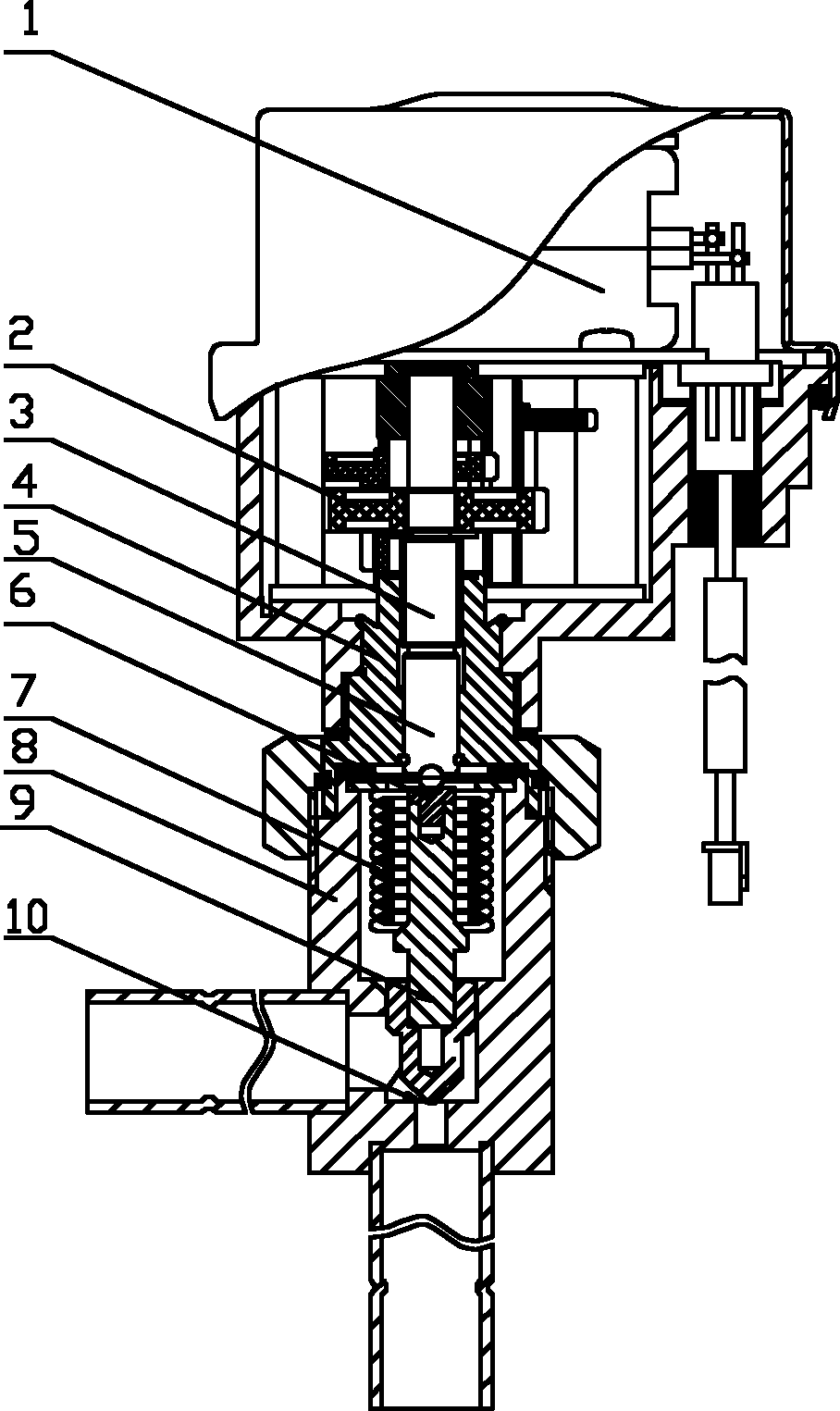
[0005] When there is a problem with the coil of the stepping motor 1 and it needs to be replaced, the valve body and the coil need to be separated. After the separation, the top of the bush 6 does not contact the screw rod 5, and the upward movement of the valve needle part 9 is no longer restricted. At this time, the system pressure of the refrigerant pipeline is relatively high, and under the action of the system pressure, the valve needle part 9 will move upward rapidly and substantially. Therefore, the upward movement of the valve needle part 9 will cause the reset elastic part 7 Excessive compression, loss or reduction of its reset ability, thereby affecting the service life of the reset elastic component 7

Method used


Image

  • Electronic expansion valve
  • Electronic expansion valve
  • Electronic expansion valve

Examples


Embodiment Construction

[0025] The core of the present invention is to provide an electronic expansion valve, the upward movement height of the needle part of the electronic expansion valve can be limited to a certain extent, and the service life of the reset elastic part can be prolonged.

[0026] In order to enable those skilled in the art to better understand the technical solutions of the present invention, the present invention will be further described in detail below in conjunction with the accompanying drawings and specific embodiments.

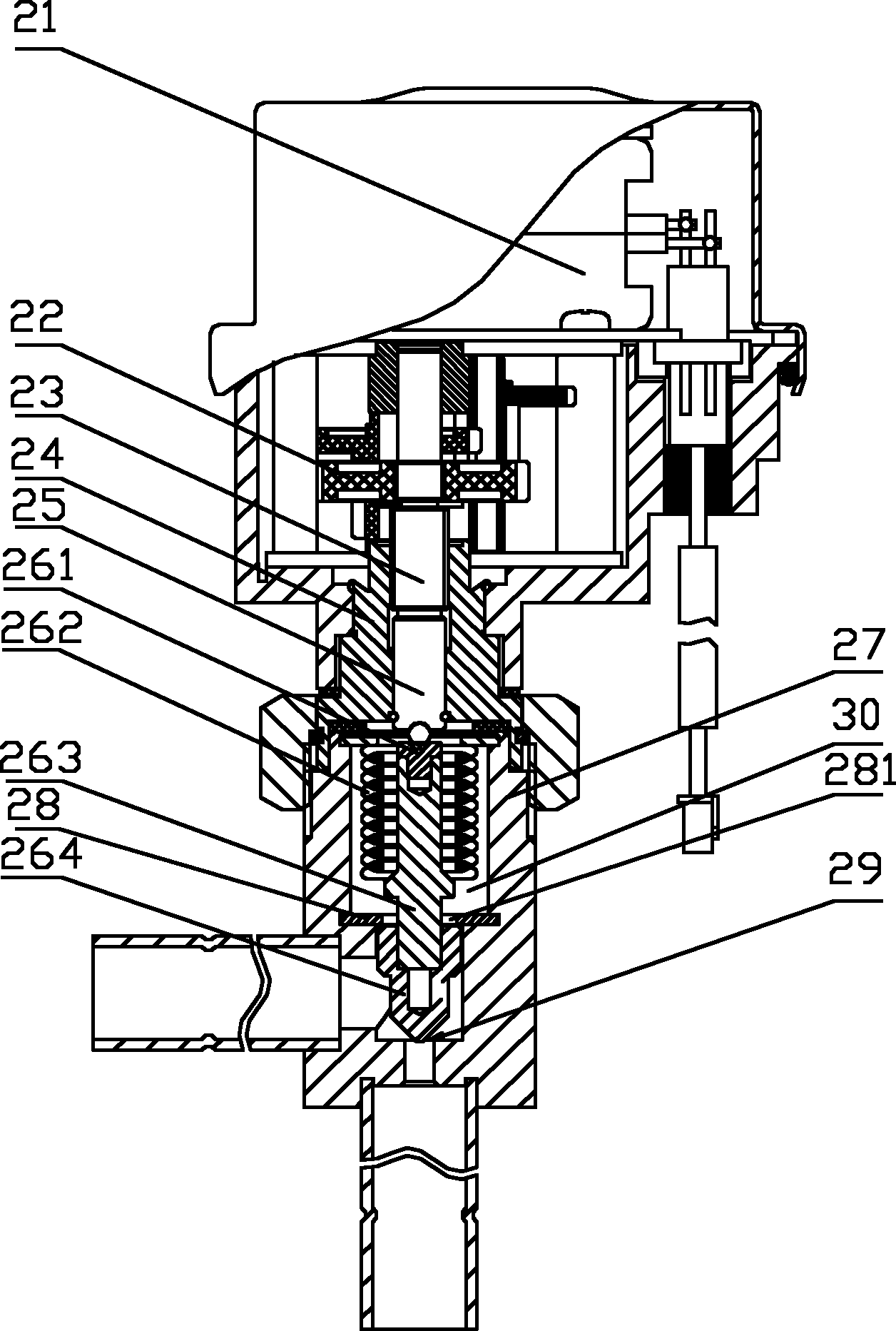
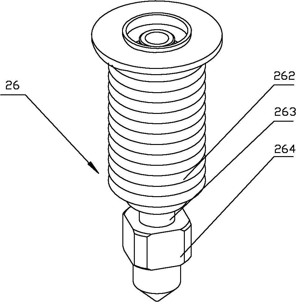
[0027] Please refer to figure 2 , image 3 and Figure 4 , figure 2 It is a structural schematic diagram of the first specific embodiment of the electronic expansion valve provided by the present invention; image 3 It is a structural schematic diagram of the valve needle part in the electronic expansion valve provided by the present invention; Figure 4 for image 3 Schematic diagram of the cross-section of the upper end of the middle valve needle; ...


PUM


Abstract

The invention discloses an electronic expansion valve, comprising a drive mechanism, a transmission mechanism, a valve seat and a valve needle component, wherein the valve needle component is provided with a valve needle axially moving along the valve cavity of the electronic expansion valve to control the openness of a valve opening, a valve rod, and an elastic component for reset. The electronic expansion valve is characterized by further comprising a limit structure arranged in the valve cavity and provided with an axial channel, and the valve needle component is provided with a transversal flange; and the limit structure is located above the flange in the case that the valve needle component moves upwards until the valve opening has the maximum openness, and the minimum radial dimension of the axial channel is less than the maximum radial dimension of the flange. The valve needle component of the electronic expansion valve cannot continue to move upwards due to the resisting of the limit structure in case of moving upwards to the position where the valve opening is the largest or slightly higher, and the valve needle component cannot greatly move upwards to compress the elastic component for reset in excess in case of coil detachment and replacement and in the other cases of needing to separate the valve needle component from other components above, thus prolonging the service life of the elastic component.

Description

technical field [0001] The invention relates to the technical field of heating, ventilating and air conditioning, in particular to an electronic expansion valve. Background technique [0002] Electronic expansion valves are widely used in throttling expansion and flow regulation of fluids. [0003] Please refer to figure 1 , figure 1 It is a structural schematic diagram of a typical deceleration electronic expansion valve for inverter air conditioners. [0004] The electronic expansion valve mainly includes a permanent magnet stepping motor 1, a gear reducer 2 with three-stage reduction, a screw rod 5 located in the nut 4 and a thread pair structure 3, a bush 6 located in the valve seat 8, and a return elastic Core components such as component 7 and valve needle component 9. The specific working principle is as follows: the electronic controller of the air-conditioning system controls the forward and reverse rotation of the rotor of the stepping motor 1 of the electronic...

Claims


Application Information

Patent Timeline
Patent Type & Authority Applications(China)
IPC IPC(8): F16K27/02F16K1/38F16K1/42F16K1/32F16K41/10F25B41/06
Inventor 舒小辉沈自成
Owner ZHEJIANG SANHUA INTELLIGENT CONTROLS CO LTD
Learn More