Hydraulic drive mechanism of heliostat

A driving mechanism and heliostat technology, applied in solar collector controllers, solar thermal devices, lighting and heating equipment, etc., can solve the problems of high gear processing cost, high maintenance cost, easy wear of gears, etc. Design, uniform and smooth movement, low cost effect

Inactive Publication Date: 2012-08-22
INST OF ELECTRICAL ENG CHINESE ACAD OF SCI
View PDF7 Cites 14 Cited by
  • Summary
  • Abstract
  • Description
  • Claims
  • Application Information

AI Technical Summary

Problems solved by technology

The transmission or driving devices of these heliostats are specially designed and processed for heliostats, and cannot be standardized and generalized.
The structure of the gear transmission box is complicated, and the processing cost of the gear is high, so the cost of the heliostat transmission box remains high. In addition, the gears are easy to wear, and the wear will seriously affect the tracking and positioning accuracy of the heliostat, and the maintenance cost is high.
For the transmission box used for large heliostats, due to the large wind load torque of large heliostats, the transmission box must output a large torque, which will inevitably result in a huge structure of the transmission box

Method used


Image

  • Hydraulic drive mechanism of heliostat
  • Hydraulic drive mechanism of heliostat
  • Hydraulic drive mechanism of heliostat

Examples


Embodiment Construction

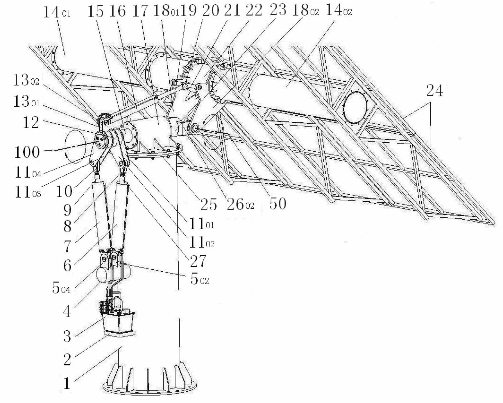
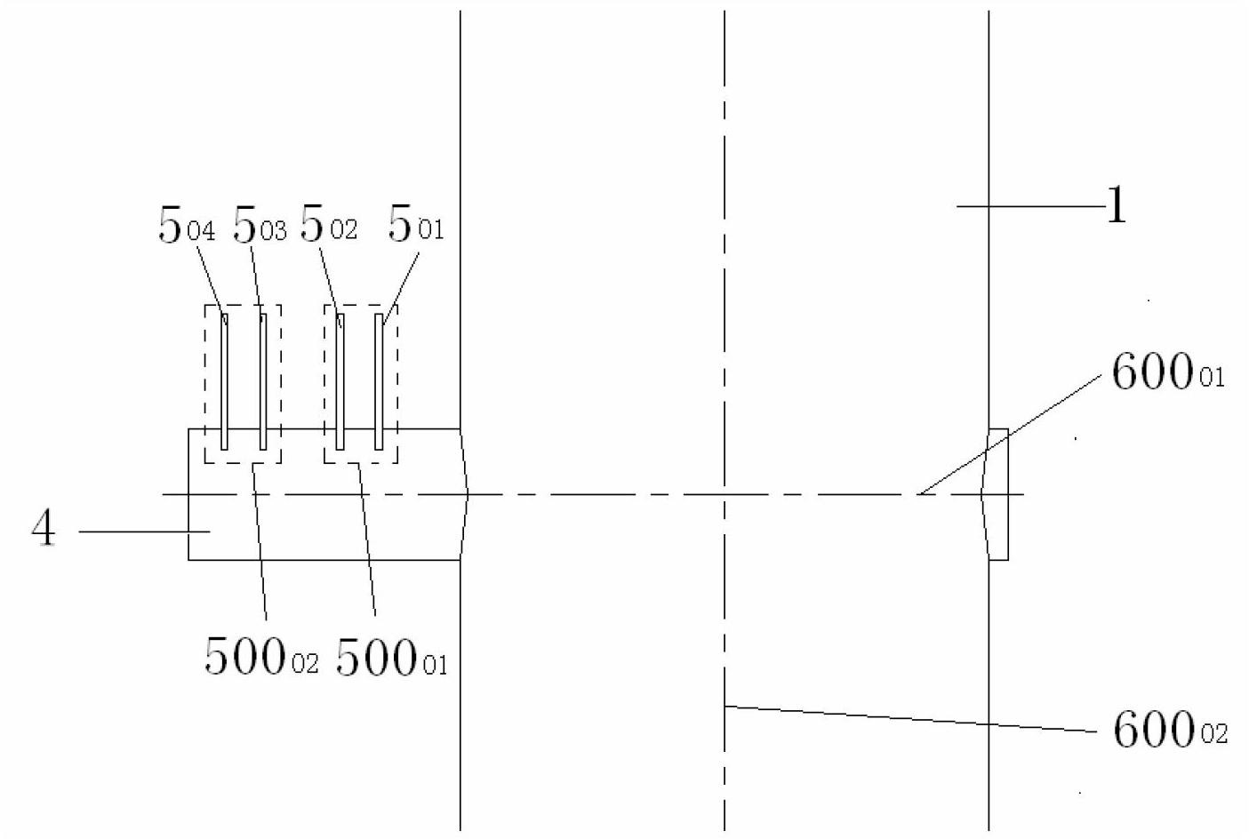
[0041] Such as figure 1 As shown, the heliostat column 1 is welded with a support beam 4 . Such as figure 2 As shown, the support beam axis 600 01 With heliostat column axis 600 02 Intersect perpendicularly. A first support plate 5 is welded along the length direction of the support beam 4 on the support beam 4 01 , the second support plate 5 02 , the third support plate 5 03 , the fourth support plate 5 04 , four support plates 5 01 、5 02 、5 03 、5 04 600 perpendicular to the support beam axis 01 ; the first support plate 5 01 and the second support plate 5 02 For the first set of support plates 500 01 , the third support plate 5 03 and the fourth support plate 5 04 For the second set of support plates 500 02 .

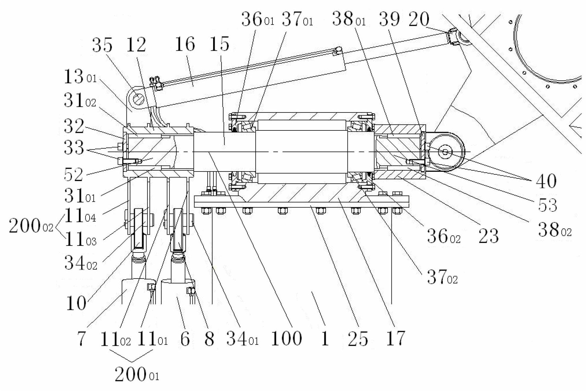
[0042] Such as figure 1 and image 3 As shown, the upper part of the heliostat column 1 is welded with a column flange 25 , and the upper part of the column flange 25 is fixedly connected with a support 17 . Such as image 3 As shown, the horizo...


PUM


Abstract

The invention discloses a hydraulic drive mechanism of a heliostat. The cylinder earrings (28, 29) of first and second linear hydraulic cylinders (6, 7) are articulated with a support plate (5) on a support beam (4), and piston rod earrings (27, 9) are articulated with a drive arm plate 11. A support arm (26) of a support fork (23) is articulated with a support plate (18) of a connection cylinder (22). A cylinder earring (44) of a third linear hydraulic cylinder (16) is articulated with an upper support plate (13), and a piston rod earring (20) is articulated with the support plate (18). The linear hydraulic cylinders (6, 7) drive a horizontal main shaft (15) to rotate, and drive a heliostat reflecting surface (24) and the linear hydraulic cylinder (16) to rotate around a horizontal main shaft axis (100); and the third linear hydraulic cylinder (16) drives the connection cylinder (22) to drive the heliostat reflecting surface (24) to rotate around a common axis (50), so that the heliostat realizes sun tracking.

Description

technical field [0001] The invention relates to a hydraulic drive mechanism of a heliostat in the field of tower-type solar thermal power generation. Background technique [0002] At present, there are mainly three types of solar thermal power generation, which are tower solar thermal power generation, trough solar thermal power generation and dish solar thermal power generation. Among them, the tower solar thermal power generation method has the advantages of high concentration ratio and high power generation efficiency. The principle of the tower solar thermal power generation method is that multiple heliostats arranged in the heliostat field track the sun, reflect and focus the sunlight on the surface of the heat absorber on the tower, where the heat transfer medium is heated to high temperature, and then through a heat exchanger to generate steam, which is used to drive a conventional steam turbine to generate electricity. In tower-type solar thermal power generation, t...

Claims


Application Information

Patent Timeline
Patent Type & Authority Applications(China)
IPC IPC(8): F24J2/38F24S50/20
CPCY02E10/47
Inventor 付向东王志峰
Owner INST OF ELECTRICAL ENG CHINESE ACAD OF SCI
Why Eureka
Try Eureka