Electronic control scanning antenna based on meta-material

A technology for scanning antennas and heterogeneous media, applied to the structural form of antennas, electrical components, and radiation elements, etc., can solve problems such as complex structures, and achieve the effect of simple operation and low cost

Inactive Publication Date: 2012-08-22
36TH RES INST OF CETC +1
View PDF6 Cites 10 Cited by
  • Summary
  • Abstract
  • Description
  • Claims
  • Application Information

AI Technical Summary

Problems solved by technology

[0006] The purpose of the present invention is to solve the problem that the traditional phased array antenna realizes the beam in the required space by feeding each array unit an

Method used


Image

  • Electronic control scanning antenna based on meta-material
  • Electronic control scanning antenna based on meta-material
  • Electronic control scanning antenna based on meta-material

Examples


specific Embodiment approach 1

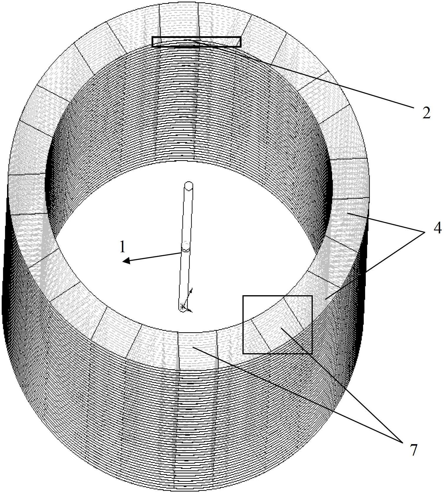
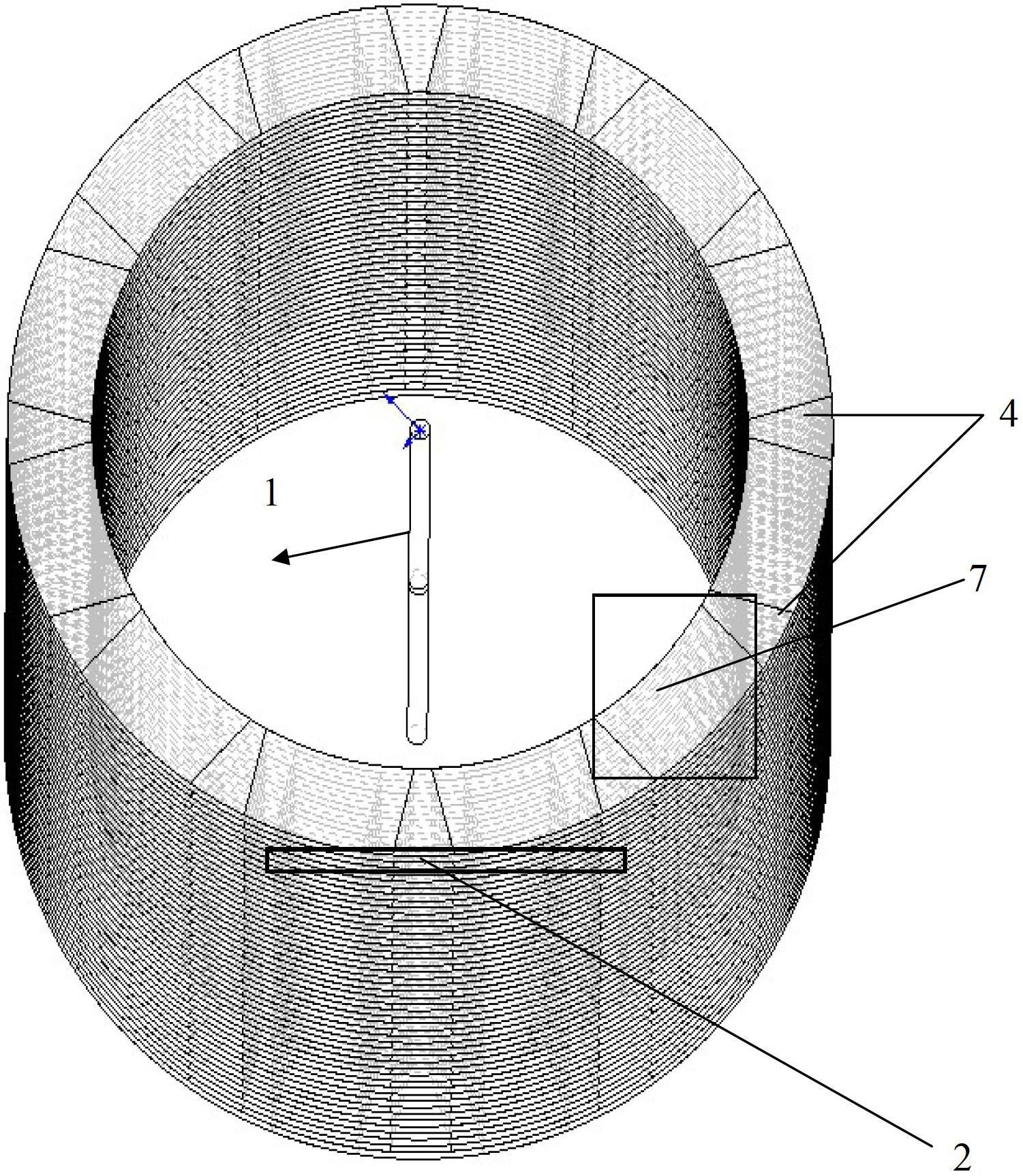
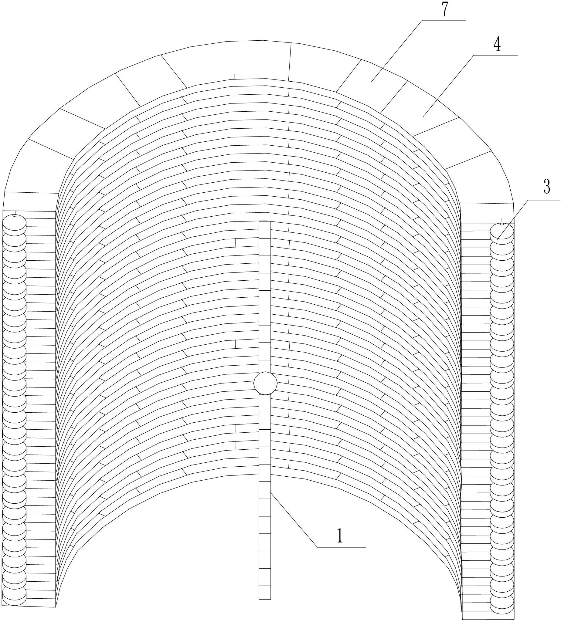
[0020] Specific implementation mode one. The following combination Figure 1 to Figure 3 This embodiment will be described. An electronically controlled scanning antenna based on an anisotropic medium described in this embodiment includes an omnidirectional antenna 1, a plurality of 3-D frequency selection structural units 2 and a plurality of varactor diodes 3;

[0021] The 3-D frequency selective structural unit 2 is composed of a sheet-shaped annular substrate 4 and a plurality of copper sheets 7;

[0022] A plurality of copper thin sheets 7 are evenly divided into two groups, wherein a plurality of copper thin sheets 7 in one group are evenly distributed on the upper surface of the sheet-shaped annular substrate 4 with the center of circle as the center, and a plurality of copper thin sheets 7 in the other group are divided into pieces The center of the ring-shaped substrate 4 is evenly distributed on its lower surface, and the copper flakes 7 on the upper surface corresp...

specific Embodiment approach 2

[0024] Specific implementation mode two. The following combination Figure 1 to Figure 3 Describe this embodiment. This embodiment is a further description of the 3-D frequency selection structure unit 2 in Embodiment 1. The inner diameter of the sheet-shaped annular substrate 4 of the 3-D frequency selection structure unit 2 in this embodiment is long It is 33.2 mm, and the outer diameter is 41.8 mm.

specific Embodiment approach 3

[0025] Specific implementation mode three. The following combination Figure 1 to Figure 3 Describe this embodiment. This embodiment is a further description of the sheet-shaped annular substrate 4 described in Embodiment 1. The relative dielectric constant of the sheet-shaped annular substrate 4 in this embodiment is 3.5, and the plate thickness is 1.274 mm. The distance between the center positions of the plates is 2.5 mm.


PUM

PropertyMeasurementUnit
The inside diameter ofaaaaaaaaaa
Outer diameteraaaaaaaaaa
Plate thicknessaaaaaaaaaa

Abstract

An electronic control scanning antenna based on a meta-material relates to an electronic control scanning antenna, aiming to solve the problem of complex structure of the traditional phased-array antenna because each array unit needs to be fed and the wave beam of the desired space is realized by changing the vibration amplitude and phase of each feed port. The electronic control scanning antenna based on the meta-material comprises an omnidirectional antenna, a plurality of 3-D frequency selection structural units and a plurality of variable capacitance diodes, wherein the variable capacitance diodes are located in a position where a variable capacitance diode interlayer is welded between the centers of two adjacent copper sheets in the vicinity of the outer sides thereof in the same positions on two adjacent layers of 3-D frequency selection structural units; the omnidirectional antenna is located in the center position of a cylindrical structure formed by the plurality of 3-D frequency selection structural units; and the height of the omnidirectional antenna is the same as that of the cylinder. The electronic control scanning antenna based on the meta-material is used for realizing multi-beam scanning.

Description

technical field [0001] The invention relates to an electronically controlled scanning antenna. Background technique [0002] The electronically controlled scanning antenna can control the main lobe pointing of the antenna pattern, change the shape of the lobe, and realize multi-beam scanning and other functions. The electronically scanned phased array antenna has fast scanning speed, flexible beam control, and strong anti-interference ability. It can simultaneously complete multiple functions such as target search, tracking, and guidance, and can work in increasingly complex and deteriorating environments. Through electronically controlled scanning, high-gain and wide-range signal transmission and reception can be realized, transmission power can be reduced, and signal coverage can be expanded. The traditional electronically controlled scanning antenna synthesizes the wave front through the phase shifter, feeds each array unit, and forms the required spatial beam by changin...

Claims


Application Information

Patent Timeline
IPC IPC(8): H01Q3/22H01Q1/36
Inventor 华军陈美良唐卓王二超杨国辉孟繁义傅佳辉吴群
Owner 36TH RES INST OF CETC
Why Eureka
Try Eureka