
Multi-level current source-type converter and multi-level injection method thereof

A current source type, multi-level technology, applied in the direction of converting AC power input to DC power output, electrical components, and output power conversion devices, etc., can solve problems such as device failure, poor operating performance, and space occupied by large-capacity capacitors. , to achieve the effect of good short-circuit resistance, reduction of current harmonic content, and reduction of requirements

Inactive Publication Date: 2012-08-22
李春生 +2
View PDF3 Cites 3 Cited by
  • Summary
  • Abstract
  • Description
  • Claims
  • Application Information

AI Technical Summary

Problems solved by technology

However, due to the poor short-circuit resistance of the voltage source converter and the immature press-fitting technology of the valve group, its operating performance in high-power applications is poor.
[0003] As the dual structure of the voltage source converter, the current source converter has good short-circuit resistance and is used in many traditional high-power applications. A large-capacity capacitor must be installed on the side as an energy buffer device. The large-capacity capacitor takes up a lot of space and is one of the main causes of device failure.

Method used


Image

  • Multi-level current source-type converter and multi-level injection method thereof
  • Multi-level current source-type converter and multi-level injection method thereof
  • Multi-level current source-type converter and multi-level injection method thereof

Examples


Embodiment 1

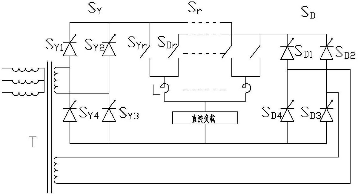
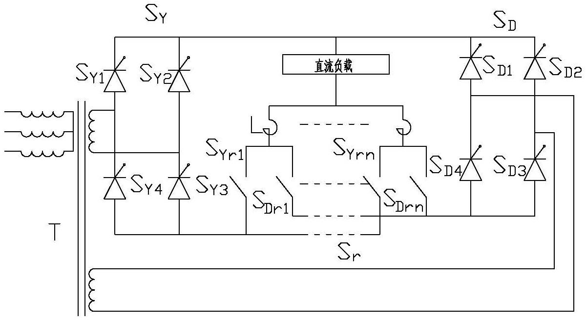
[0021] A multilevel current source converter, see figure 1 with figure 2 , the converter includes multiple sets of injection circuits S for injecting current into the DC load r and a transformer T with two single-phase power outputs of different phases, and the two single-phase power supplies are respectively connected to a fully-controlled bridge S Y and S D ; The injection circuit includes two injection switches S Yr , S Dr and a reactor L, one of which injects the switch S Yr A fully controlled bridge S connected to a single-phase power supply through a DC load after being connected in series with the reactor L Y , another injected switch S Dr After being connected in series with the reactor L, the fully controlled bridge S is connected to another single-phase power supply through a DC load D .

[0022] The transformer with two different-phase single-phase power output is a three-phase-two-phase balanced transformer, and the phase difference of the two-phase AC out...

Embodiment 2

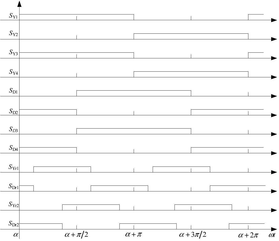
[0025] A multi-level injection method based on multi-level current source converter, see figure 1 and embodiment 1, the multi-level current source converter includes multiple sets of injection circuits for injecting current into DC loads and a three-phase-two-phase balance transformer, and the phase difference between the two-phase AC output voltages is 90 o , the two-phase AC output is respectively connected with a fully-controlled bridge; the injection circuit includes two injection switches and a reactor, one of which is connected in series with the reactor through a DC load to a fully-controlled bridge with one-phase AC output, and the other A fully-controlled bridge that connects another phase of AC output through a DC load after the injection switch and reactor are connected in series, see image 3 with Figure 4 , the multi-level injection method is: two injection switches are synchronized with the fundamental frequency of the fully-controlled bridge power supply conne...


PUM


Abstract

The invention relates to a multi-level current source-type converter and a multi-level injection method thereof; the multi-level current source-type converter comprises a three phase-two phase balance transformer, two groups of single-phase fully controlled bridges and a multi-injection circuit; all switching devices in the converter are fully controlled inverse resistance devices; the switch combination of the injection circuit switches the inductance current of all injection branches at the output ends of two groups of main bridges; the output current of each group of thyristor main bridge is cascade multi-level pulse current which is twice of power supply base wave frequency and is provided with a zero value interval; and the corresponding main bridge devices are switched in the zero value interval of current. The structure of the injection circuit provides a zero current phase-shift condition for the main bridges, so that the switching losses of the devices of the main circuit are lower; and the direct current is in cascade changes, the capacity of buffer capacitance on an alternating current side can be greatly reduced.

Description

technical field [0001] The present invention relates to the technical field of power electronics, in particular to a multi-level current source converter based on a three-phase-two-phase balanced transformer and a multi-level injection method thereof. Different zero-current injections are set in two level injection branches The time period is used as the commutation point of the controllable rectifier bridge, thereby realizing the zero-current commutation of the controllable rectifier bridge. Background technique [0002] In recent years, the voltage source converter of the fully controlled device IGBT has been widely used in the field of medium and small power AC-DC conversion. However, due to the poor short-circuit resistance of the voltage source converter and the immature press-fitting technology of the valve group, its operating performance in high-power applications is poor. [0003] As the dual structure of the voltage source converter, the current source converter h...

Claims


Application Information

Patent Timeline
Patent Type & Authority Applications(China)
IPC IPC(8): H02M7/483
Inventor 李春生杨宝峰马方生
Owner 李春生
Learn More