
Shuttle pushing mechanism of small-cam circular weaving machine

A circular loom and small cam technology, which is applied to circular looms, looms, textiles, etc., can solve the problems of increased energy consumption, high noise, and large resistance, and can reduce energy consumption, noise, and reverse. The effect of resistance

Active Publication Date: 2013-12-11
雁峰集团有限公司
View PDF6 Cites 0 Cited by
  • Summary
  • Abstract
  • Description
  • Claims
  • Application Information

AI Technical Summary

Problems solved by technology

[0002] The small cam circular looms manufactured and used at present place the friction wheel under the front end of the advancing direction of the propulsion wheel, and use spring tension to keep the friction wheel close to the track all the time, and push it forward by the friction bracket on the propulsion arm. The reverse resistance when it advances is due to the angle of the force. The greater the resistance, the greater the friction wheel pressing on the track, the greater the friction force, the greater the friction force, the greater the resistance, so the chain reaction is very easy to cause vibration, so that the warp thread passes through the push wheel and the shuttle. The tail wheel will cause disconnection, and the noise will be loud, and the resistance will increase the energy consumption

Method used


Image

  • Shuttle pushing mechanism of small-cam circular weaving machine
  • Shuttle pushing mechanism of small-cam circular weaving machine
  • Shuttle pushing mechanism of small-cam circular weaving machine

Examples


Embodiment Construction

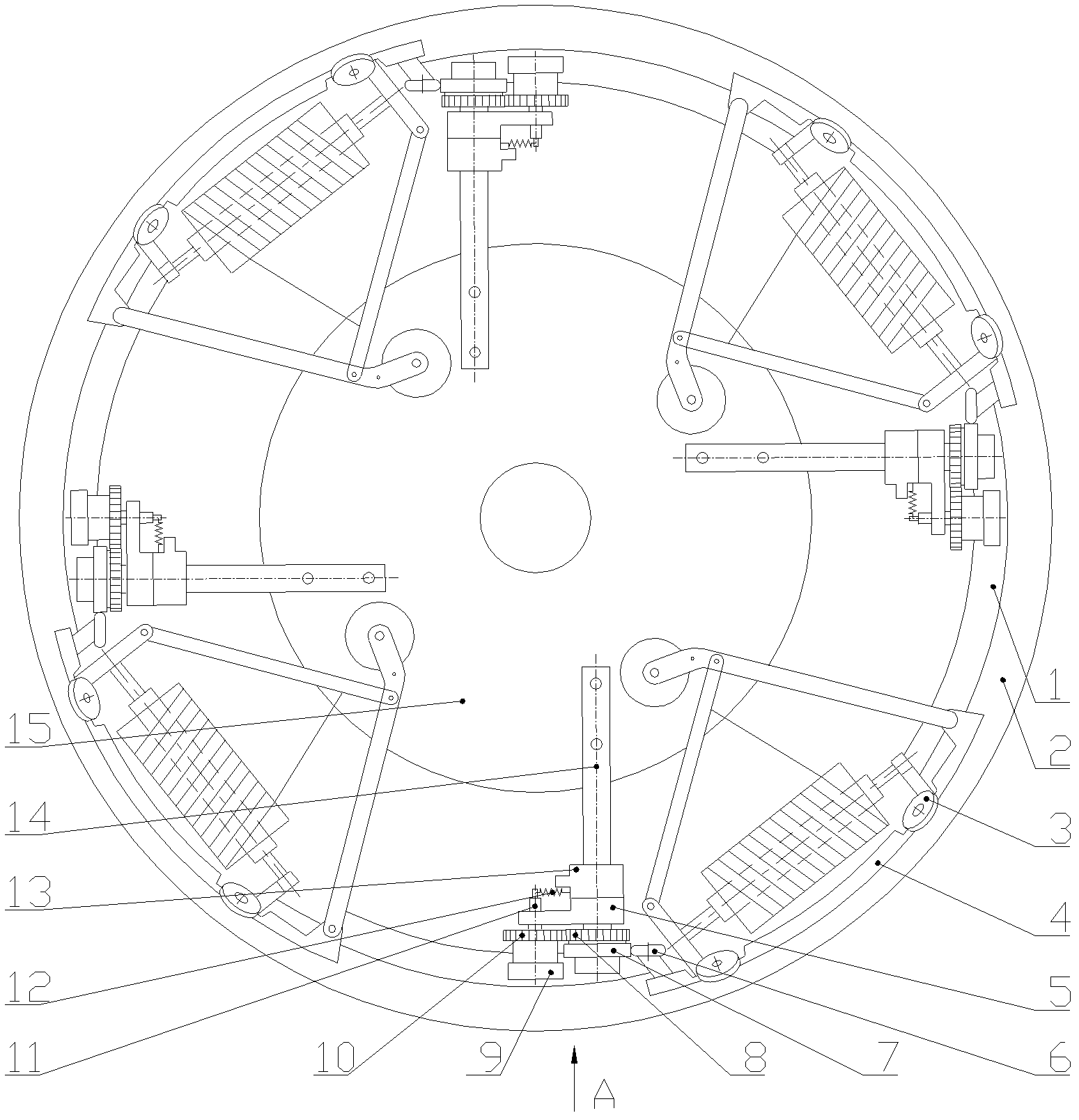
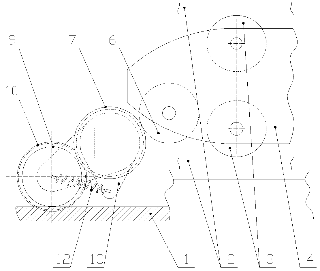
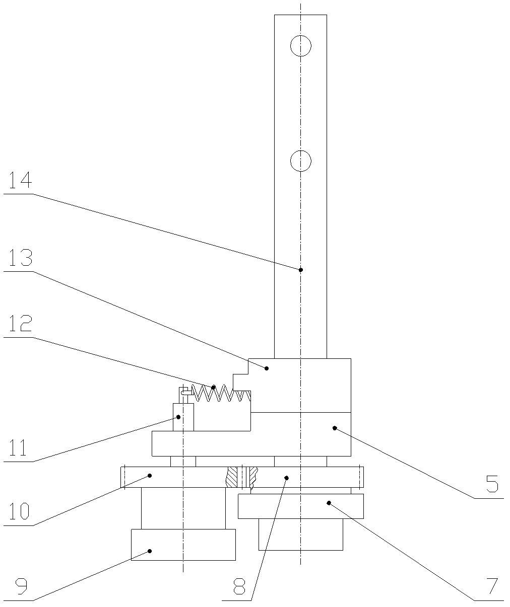
[0014] Such as Figure 1 to Figure 3 Shown is the embodiment of the push shuttle mechanism of the small cam circular loom of the present invention,

[0015] refer to figure 1 , figure 2 and image 3 , 1-friction wheel track, 2-shuttle track, 3-shuttle wheel, 4-shuttle, 5-friction wheel bracket, 6-shuttle tail wheel, 7-propelling wheel, 8-passive gear, 9-friction wheel, 10- Driving gear, 11-friction wheel mandrel, 12-spring, 13-spring seat, 14-propelling arm, 15-propelling disc.

[0016] The propulsion arm 14 that is fixed on the propulsion disc 15 is connected with the propulsion wheel 7 in rotation, and the front of the propulsion wheel 7 is in rolling contact with the shuttle tail wheel 6, and the friction wheel 9 is arranged on the rear lower side position of the propulsion wheel 7, and is fixed on the friction wheel. The driving gear 10 on the 9 meshes with the driven gear 8 fixed on the propulsion wheel 7, the friction wheel 9 is connected in rotation with the fricti...


PUM


Abstract

The invention discloses a shuttle pushing mechanism of a small-cam circular weaving machine, comprising a propulsion arm, wherein the outer end of the propulsion arm is rotationally connected with a propulsion wheel, the propulsion wheel is in rolling contact with a shuttle tail wheel at the front end of the propulsion wheel, a driven gear is fixedly mounted at the inner end of the propulsion wheel, the propulsion arm is rotationally connected with a friction wheel bracket in the inner side of the driven gear, a spring seat of the propulsion arm is fixedly mounted on the inner side of the friction wheel bracket, the rear side of the friction wheel bracket is fixedly connected with a friction wheel mandrel, a friction wheel is rotationally connected to the friction wheel mandrel, the friction wheel is arranged at the rear side of the propulsion wheel and is lower than the propulsion wheel, a spring is arranged between the inner end of the friction wheel mandrel and the spring seat, the friction wheel is in rolling contact with a friction wheel track, a driving gear is fixedly mounted at the inner end of the friction wheel, and the driving gear is meshed with the driven gear. According to the shuttle pushing mechanism, the reversal resistance from the friction wheel track in the operating state is greatly reduced, no vibration is caused, and warp yarns are enabled to smoothly pass through between the propulsion wheel and the shuttle tail wheel without being broken.

Description

technical field [0001] The invention relates to a component of a plastic circular loom, in particular to a shuttle pushing mechanism of a small cam circular loom. Background technique [0002] The small cam circular looms manufactured and used at present place the friction wheel under the front end of the advancing direction of the propulsion wheel, and use spring tension to keep the friction wheel close to the track all the time, and push it forward by the friction bracket on the propulsion arm. The reverse resistance when it advances is due to the angle of the force. The greater the resistance, the greater the friction wheel pressing on the track, the greater the friction force, the greater the friction force, the greater the resistance, so the chain reaction is very easy to cause vibration, so that the warp thread passes through the push wheel and the shuttle. When the tail wheel is turned, it will cause disconnection, and the noise will be loud, and the resistance will i...

Claims


Application Information

Patent Timeline
Patent Type & Authority Patents(China)
IPC IPC(8): D03D49/46D03D37/00
Inventor 陈志淡邹虎生陈向荣陈庆楷陈卫国
Owner 雁峰集团有限公司
Learn More