
Lubricating device with electromagnetic quantity control mechanism for rotary kiln wheel shaft

A technology of a quantity control mechanism and a lubricating device, which is applied in the field of rotary kilns, can solve the problems of poor lubricating oil use effect, difficult control of lubricating oil delivery amount, and poor lubricating effect.

Inactive Publication Date: 2021-04-27
陈怀圣
View PDF7 Cites 0 Cited by
  • Summary
  • Abstract
  • Description
  • Claims
  • Application Information

AI Technical Summary

Problems solved by technology

[0003] However, today's rotary kiln wheel shaft lubrication device can automatically control the delivery time and delivery volume of lubricating oil through the solenoid valve, but for the direct spraying type, the short-term spraying will make the spraying uneven, and the long-term spraying will waste lubricating oil. It is also difficult to control the amount of lubricating oil delivered, and the lubricating oil needs to be continuously circulated by directly immersing the wheel shaft. In this way, the power consumption of electrical appliances is large, and the consumption of crude oil is also large, and the use effect of the lubricating oil after circulation is not good. Well, before the lubricating oil is used, due to the influence of the environment on the crude oil itself, the uniformity of the lubricating oil will change, making the lubricating effect worse

Method used


Image

  • Lubricating device with electromagnetic quantity control mechanism for rotary kiln wheel shaft
  • Lubricating device with electromagnetic quantity control mechanism for rotary kiln wheel shaft
  • Lubricating device with electromagnetic quantity control mechanism for rotary kiln wheel shaft

Examples


Embodiment 1

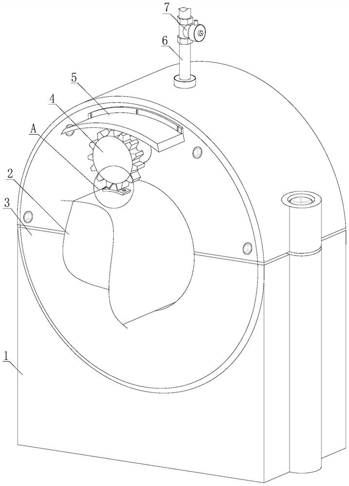
[0030] see figure 1 , the rotary kiln wheel shaft is equipped with a lubrication device with an electromagnetic control mechanism, including a support seat 1, a wheel shaft 2, a wheel shaft seat 3, an oiling mechanism 4, a protective cover 5, a connecting pipe 6 and a solenoid valve 7, and the wheel shaft seat 3 is installed on the support seat 1, the axle 2 is inserted into the middle of the axle seat 3, the oiling mechanism 4 is located at the upper end of the axle 2 and runs through the axle seat 3, the protective cover 5 is installed on the upper side of the outer end of the oiling mechanism 4 on the axle seat 3, and the connection pipe 6 The lower end is communicated with the middle part of the upper end of the axle seat 3, the upper end of the connecting pipe 6 is connected with the solenoid valve 7, and the other end of the solenoid valve 7 is connected with the hydraulic pump and the lubricating oil tank in turn.

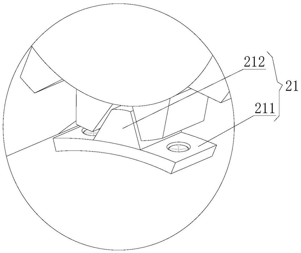
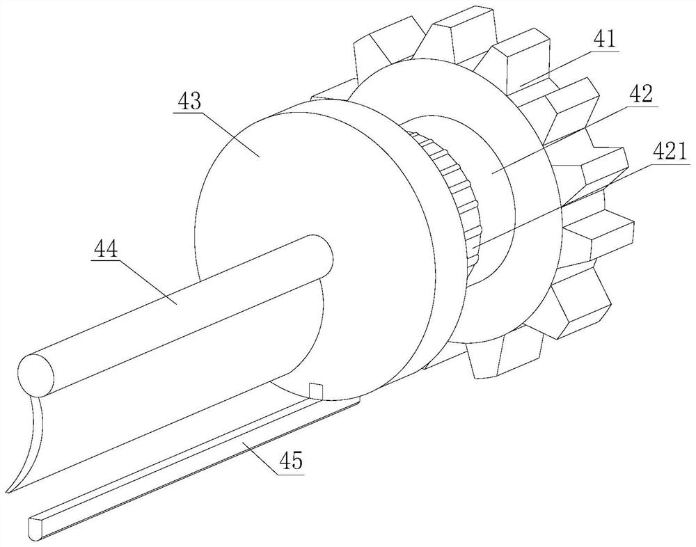
[0031] see Figure 2-3, the rotary kiln wheel shaft u...

Embodiment 2

[0038] see figure 1 , the rotary kiln wheel shaft is equipped with a lubrication device with an electromagnetic control mechanism, including a support seat 1, a wheel shaft 2, a wheel shaft seat 3, an oiling mechanism 4, a protective cover 5, a connecting pipe 6 and a solenoid valve 7, and the wheel shaft seat 3 is installed on the support seat 1, the axle 2 is inserted into the middle of the axle seat 3, the oiling mechanism 4 is located at the upper end of the axle 2 and runs through the axle seat 3, the protective cover 5 is installed on the upper side of the outer end of the oiling mechanism 4 on the axle seat 3, and the connection pipe 6 The lower end is communicated with the middle part of the upper end of the axle seat 3, the upper end of the connecting pipe 6 is connected with the solenoid valve 7, and the other end of the solenoid valve 7 is connected with the hydraulic pump and the lubricating oil tank in turn.

[0039] see Figure 2-3 , the rotary kiln wheel shaft ...


PUM


Abstract

The invention discloses a lubricating device with an electromagnetic quantity control mechanism for a rotary kiln wheel shaft. The lubricating device with the electromagnetic quantity control mechanism for the rotary kiln wheel shaft comprises a supporting seat, the wheel shaft, a wheel shaft seat, an oiling mechanism, a protective cover, a connecting pipe and an electromagnetic valve. The lubricating device with the electromagnetic quantity control mechanism for the rotary kiln wheel shaft has the beneficial effects that the rotating period of a driven gear can be controlled by setting the number of gear teeth of a driven gear, so that regular interval oiling lubrication is achieved; lubricating oil stock solution is reasonably utilized, the electric power loss of an electric appliance for circulating oiling is reduced, rotation of the wheel shaft is skillfully utilized, lubricating oil flows out of an oil storage bin, lubricating is carried out on the surface of the wheel shaft, and the lubricating time coincides with the time that the wheel shaft rotates by one circle, so that the outer surface of the wheel shaft is completely and uniformly coated with the lubricating oil, and the lubricating effect is further improved; and a first repelling piece repels a second repelling piece, a moving piece moves in the direction away from the first repelling piece, a lubricating oil outlet is blocked, lubrication is stopped, and when a stirring piece rotates to pass through the lubricating oil, the lubricating oil is evenly stirred, and therefore the uniformity of the lubricating oil is improved, and then the lubricating effect is improved.

Description

technical field [0001] The invention relates to the technical field of a rotary kiln, in particular to a lubricating device with an electromagnetic control mechanism for a wheel shaft of a rotary kiln. Background technique [0002] Rotary kiln refers to rotary calcining kiln (commonly known as rotary kiln), which belongs to the category of building materials equipment. Rotary kiln can be divided into cement kiln, metallurgical chemical kiln and lime kiln according to different materials. Cement kilns are mainly used for calcining cement clinker, which can be divided into two categories: dry production cement kiln and wet production cement kiln. Metallurgical and chemical kilns are mainly used for magnetization roasting of lean iron ore in iron and steel plants in the metallurgical industry; oxidative roasting of chromium and nickel-iron ore; roasting of high-alumina bauxite in refractory plants and clinker and aluminum hydroxide in aluminum plants; roasting of chromium ore ...

Claims


Application Information

Patent Timeline
IPC IPC(8): F16N7/38F16N39/00F27B7/22
CPCF16N7/38F16N39/00F27B7/22
Inventor 陈怀圣
Owner 陈怀圣
Learn More