Electric valve

An electric valve, valve shaft technology, applied in the direction of lift valve, valve details, valve device, etc., can solve the problems of increased sliding frictional resistance, low machining accuracy, easy deformation, etc., and achieve the effect of reducing sliding frictional resistance.

Active Publication Date: 2012-08-29
FUJIKOKI MFG CO LTD
View PDF7 Cites 21 Cited by
  • Summary
  • Abstract
  • Description
  • Claims
  • Application Information

AI Technical Summary

Problems solved by technology

[0012] However, the processing accuracy of the valve body assembled in this way is lower than that of the cutting workpiece. In addition, since the stress during the stamping process is released due to the heat generated when the parts are joined, it has disadvantages such as easy deformation. The center line of the valve port) is prone to deviation or inclination relative to the common axis of rotation of the rotor, valve shaft and valve frame
In this way, if the center line of the valve seat (the valve port provided on it) deviates or inclines relative to the rotation axis (hereinafter referred to as the axis deviation of the valve port, etc.), the valve core adapts to the position when the valve is opened and closed. Inserting and disengaging at the valve port (or valve seat), the valve core is also prone to misalignment or inclination with respect to the rotation axis, and then there is the eccentricity caused by the compression coil spring, and the compression coil spring near the valve opening and closing The problem of increased sliding frictional resistance
[0013] This kind of problem is likely to occur especially when the setting load of the compression coil spring is increased with the increase of the diameter of the valve port (increased flow rate).

Method used


Image

  • Electric valve
  • Electric valve
  • Electric valve

Examples


Embodiment Construction

[0050] Embodiments of the present invention will be described below with reference to the drawings.

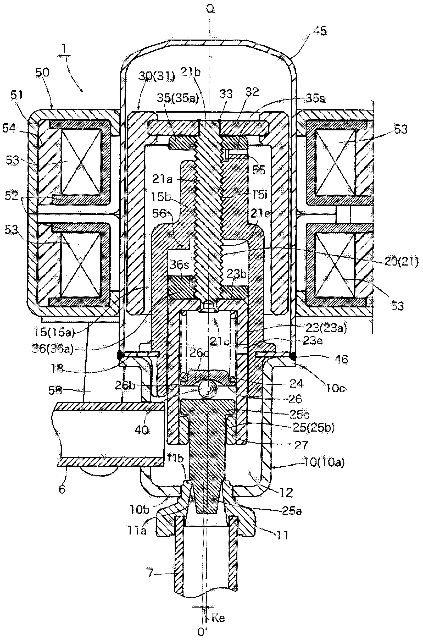
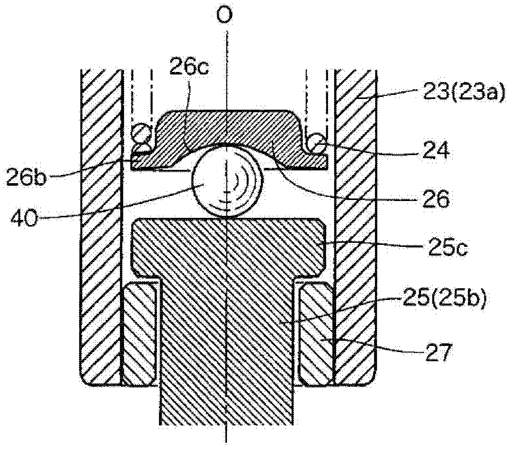
[0051] figure 1 , figure 2 It is a longitudinal sectional view and an enlarged view of main parts respectively showing an embodiment of the electric valve of the present invention.

[0052] The illustrated electric valve 1 has: a bottomed cylindrical valve body 10 with an opening above it; a housing 45 whose lower end is in sealing engagement with the valve body 10; a guide rod with a flange-shaped circular plate 18 15, which is welded and fixed on the upper end surface 10c of the valve body 10; the valve shaft 20, which is screwed with the internal thread portion 15i formed on the small diameter upper portion 15b of the guide rod 15; the rotor 30, which is fixed on the valve shaft 20 an upper portion; and a stator 50 fitted on the outer periphery of the housing 45 to rotationally drive the rotor 30 .

[0053] Here, the rotor 30 , the stator 50 , the internal thread portio...


PUM


Abstract

The invention provides an electric valve, which can be used to reduce the sliding friction resistance close to the compression spiral spring during the opening and closing of the valve possibly, even when the decentration of the compression spiral spring and the shaft deviation of the valve occur. A coiling end of a lower side of the compression spiral spring (24) is clipped by a spring supporting member (26), and a spherical-shaped object (40) having two parts and the spring supporting member (26) as well as the valve core (25) in a point-contact manner is disposed between the same two members. A concave part (26c) used for adjusting the valve core is formed by a spherical-shaped surface, an ellipsoid-shaped surface, and a cone-shaped surface. The deepest part of the concave part is disposed on an centre of the lower surface of the spring supporting member (26) approximately. By using the concave part (26c) used for adjusting the valve core and the spherical-shaped object (40), the sliding friction resistance can be reduced.

Description

technical field [0001] The invention relates to an electric valve installed in a heat pump refrigeration and heating system, etc., and in particular to an electric valve which uses the rotation of the rotor and uses screw feed to make the valve core and the valve seat contact and separate. Background technique [0002] As such an electric valve, there is an electric valve having: a valve shaft with a valve core provided at its lower end; a valve body provided with a guide rod having a cylindrical portion inserted into the valve shaft; The valve seat is separated from the valve core; the casing is engaged with the valve body; and the valve shaft lifting drive mechanism includes a rotor integrated with the valve shaft arranged in the casing, and is used to rotate and drive the rotor. The stator arranged on the outer periphery of the housing, the internal thread portion provided on the side of the guide rod, and the external thread portion provided on the side of the valve shaf...

Claims


Application Information

Patent Timeline
IPC IPC(8): F16K1/00F16K31/04F16K27/02
Inventor 中野睦仁菅沼威
Owner FUJIKOKI MFG CO LTD
Why Eureka
Try Eureka