Highlight maintaining method for liquid crystal display

A liquid crystal display, bright spot technology, applied in instruments, nonlinear optics, optics, etc., can solve problems such as low success rate, and achieve the effect of improving success rate, avoiding too large gaps, and solving low success rate

Active Publication Date: 2012-08-29
BOE TECH GRP CO LTD +1
View PDF4 Cites 18 Cited by
  • Summary
  • Abstract
  • Description
  • Claims
  • Application Information

AI Technical Summary

Problems solved by technology

[0004] The embodiment of the present invention provides a method for repairing bright spots of liquid crystal displays, which solves the technical problem of low success rate of existing repair methods

Method used


Image

  • Highlight maintaining method for liquid crystal display
  • Highlight maintaining method for liquid crystal display
  • Highlight maintaining method for liquid crystal display

Examples


Embodiment 1

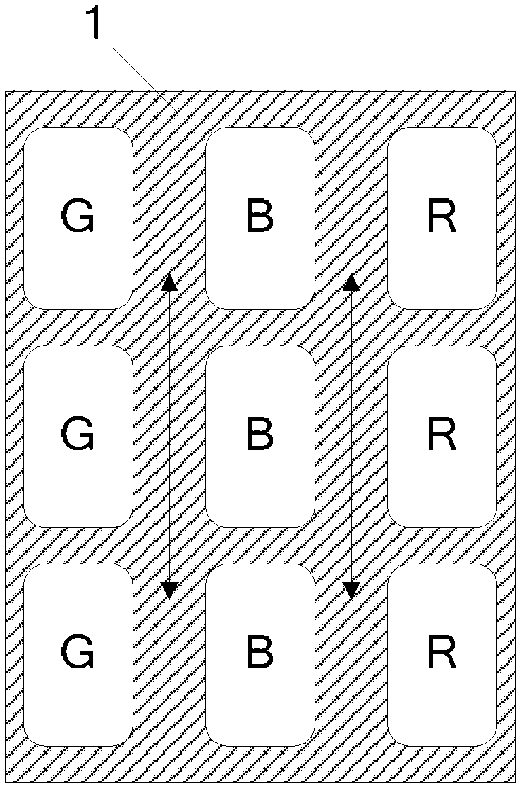
[0034] Such as figure 1 As shown, taking a liquid crystal panel with sub-pixels arranged in a square matrix as an example, the blue sub-pixels in the middle of the figure are sub-pixels to be repaired. In the liquid crystal display bright spot repair method provided by the embodiment of the present invention, the laser is used to perform the following steps when repairing the blue sub-pixel:

[0035] Preferably, the laser wavelength used in the embodiment of the present invention is 355nm.

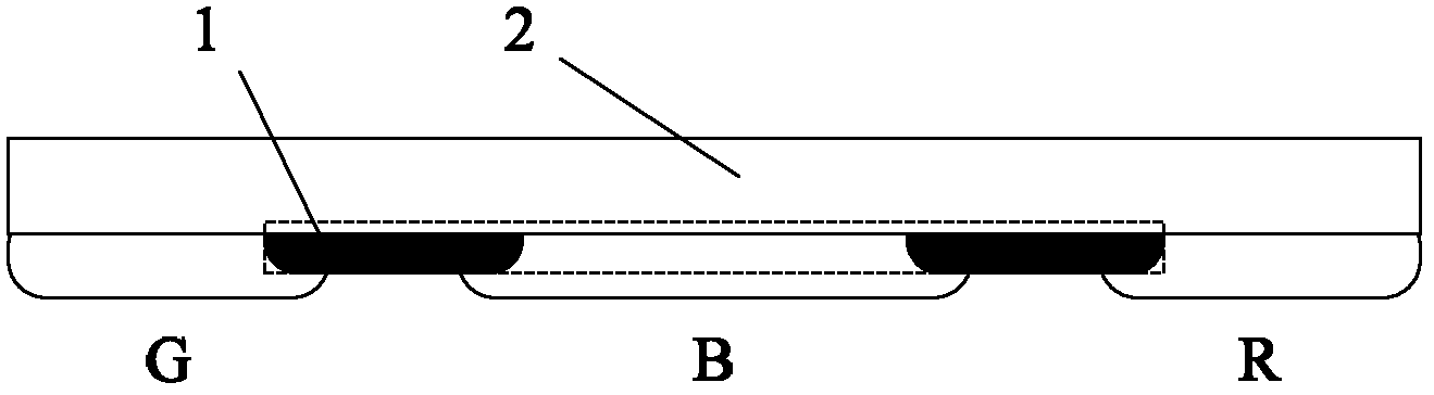
[0036] S101: Perform aging on the color filter of the repaired sub-pixel and the black matrix (black matrix, BM) 1 around it.

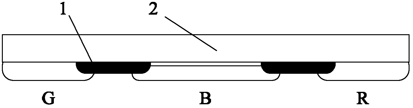
[0037] Specifically, laser is used to preheat the color filter of the repaired sub-pixel and the surrounding black matrix 1 to achieve the purpose of aging. figure 2 The dotted box in the middle indicates the granulated part. As a preferred solution, the intensity of the laser in this process is 2 to 3 A.U, where A.U (Arbitrary Unit, arbitrary unit) represents...

Embodiment 2

[0059] This embodiment is basically the same as Embodiment 1, the difference is: as Figure 5 As shown, the sub-pixels to be repaired in this embodiment are green, and the bright spot repair method is to use laser to perform the following steps:

[0060] S201: Perform aging on the color filter of the repaired sub-pixel and the black matrix 1 around it.

[0061] Specifically, the laser is used to preheat the color filter of the sub-pixel to be repaired and the black matrix 1 around it, so as to achieve the purpose of aging. As a preferred solution, the intensity of the laser during this process is 2 to 3 A.U.

[0062] It has been verified by experiments that if the laser energy is too low, the subsequently formed gap will be incomplete, and if the laser energy is too high, it will cause defective pixels in the sub-pixels around the sub-pixel.

[0063] S202: Forming a gap between the color filter and the glass substrate, using a laser with an intensity of 17 to 19 A.U.

[006...

Embodiment 3

[0083] This embodiment is basically the same as Embodiment 1, the difference is: as Image 6 As shown, the sub-pixels to be repaired in this embodiment are red, and the bright spot repair method is to use laser to perform the following steps:

[0084] S301: Perform aging on the color filter of the repaired sub-pixel and the black matrix 1 around it.

[0085] Specifically, the laser is used to preheat the color filter of the sub-pixel to be repaired and the black matrix 1 around it, so as to achieve the purpose of aging. As a preferred solution, the intensity of the laser during this process is 2 to 3 A.U.

[0086] It has been verified by experiments that if the laser energy is too low, the subsequently formed gap will be incomplete, and if the laser energy is too high, it will cause defective pixels in the sub-pixels around the sub-pixel.

[0087] S302: Forming a gap between the color filter and the glass substrate, using a laser with an intensity of 23 to 25 A.U.

[0088] ...


PUM

PropertyMeasurementUnit
Wavelengthaaaaaaaaaa

Abstract

The embodiment of the invention discloses a highlight maintaining method for a liquid crystal display. According to the maintaining method, a color diaphragm plate of the liquid crystal display is maintained and comprises a base plate as well as a black matrix and red-green-blue color diaphragms arranged on the base plate, wherein red-green-blue color diaphragms are separated by the black matrix, and laser is utilized for implementing the following steps of: ageing the color diaphragms of sub pixel points to be maintained and the black matrix at the peripheries of the sub pixel points; forming seams between the color diaphragms and a glass base plate; granulating the black matrixes at the peripheries of the color diaphragms to generate black particles; dispersing the black particles at the peripheries of the color diaphragms into the seams; using the laser with the strength being 12-17A.U if the color diaphragms of the sub pixel points are blue in the process that the seams are formed between the color diaphragms and the glass base plate; using the laser with the strength being 17-19A.U if the color diaphragms of the sub pixel points are green in the process that the seams are formed between the color diaphragms and the glass base plate; and using the laser with the strength being 23-25A.U if the color diaphragms of the sub pixel pints are red in the process that the seams are formed between the color diaphragms and the glass base plate. The highlight maintaining method is applied to the improvement of the highlight maintenance.

Description

technical field [0001] The invention belongs to the technical field of liquid crystal panel manufacturing, and in particular relates to a method for maintaining bright spots of a liquid crystal display. Background technique [0002] With the continuous development of electronic technology, liquid crystal displays have become the most common display devices. In the manufacturing process of LCD panels, sometimes a certain sub-pixel is a bright spot, which affects the display quality, so it is necessary to repair the bright spot into a dark spot. The traditional welding repair method has gradually been replaced due to the frequent occurrence of low bright spots. [0003] At present, lasers are usually used to cover the black matrix on the color film to repair bright sub-pixels. However, the existing maintenance methods all use lasers with the same energy for red, green and blue color films, which leads to the technical problem of low success rate of bright spot maintenance. ...

Claims


Application Information

Patent Timeline
IPC IPC(8): G02F1/13G02F1/1335
Inventor 钮曼萍吴涛张钟石
Owner BOE TECH GRP CO LTD
Why Eureka
Try Eureka