
Cup bottom paper cutting and delivering mechanism of high-speed paper cup machine

A paper cup machine and cup bottom technology, applied in metal processing and other directions, can solve the problems affecting the service life of the die and cutting quality, the deviation of the die, and the inconvenience of changing the die, so as to improve the service life and cutting quality, improve the The effect of service life

Active Publication Date: 2012-09-05
瑞安市胜利机械有限公司
View PDF7 Cites 8 Cited by
  • Summary
  • Abstract
  • Description
  • Claims
  • Application Information

AI Technical Summary

Problems solved by technology

In the cutting structure of the cup bottom, when the upper and lower dies are closed and cut the bottom paper of the cup, the positioning must be accurate. Since the eccentric wheel seat rod is transmitted to the sliding seat, it is pushed obliquely, and the upper guide alone will quickly cause the mold to deviate, which will affect the The service life and cutting quality of the knife die
It is necessary to remove the upper guide structure when replacing the cutting die, which has defects such as cumbersome assembly and inconvenient replacement of the die.

Method used


Image

  • Cup bottom paper cutting and delivering mechanism of high-speed paper cup machine
  • Cup bottom paper cutting and delivering mechanism of high-speed paper cup machine
  • Cup bottom paper cutting and delivering mechanism of high-speed paper cup machine

Examples


Embodiment Construction

[0014] The present invention will be further described below in conjunction with accompanying drawing embodiment:

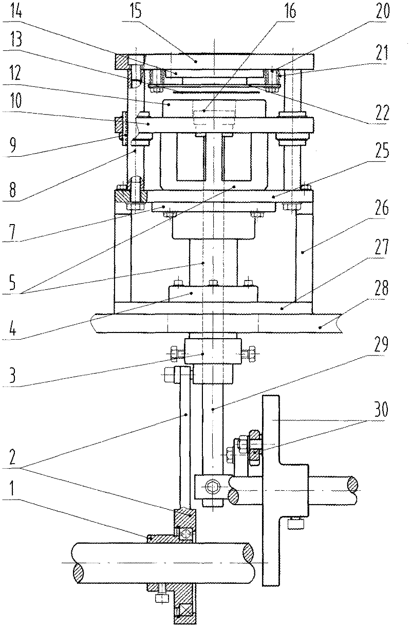
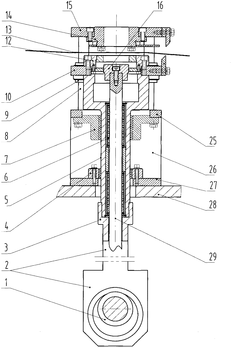
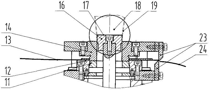
[0015] The technical solution adopted by the present invention to solve the above-mentioned technical problems is: a cup bottom paper cutting mechanism of a high-speed paper cup machine is composed of a cutting structure and a pushing structure. The cutting structure mainly includes that the eccentric wheel 1 is movably connected with the wheel seat post 2 and the seat cover 3 through the bearing, the seat cover is fixedly connected with the sliding seat 5, the inner holes of the lower guide seat 4 and the middle guide seat 7 are provided with guide sleeves, and are connected with the outer surface of the sliding seat 5. The upper end of the sliding seat 5 is fixedly connected to the sliding plate 10, the sliding plate is square, and the inner holes at the four corners are provided with upper guide sleeves 9, each upper guide sleeve is in clearance fit with the gu...


PUM


Abstract

The invention relates to a cup bottom paper cutting and delivering mechanism of a high-speed paper cup machine. Guide sleeves are respectively arranged in the inner holes of a lower guide holder and a middle guide holder and are in clearance fit with a sliding seat in outer diameter, a sliding plate is square, upper guide sleeves are arranged in the inner holes of four corners and are in clearance fit with guide pillars, and an eccentric wheel is driven by a driving mechanism to enable the sliding plate to move vertically; and the guide pillars are used for positioning while the sliding plate is used for guiding, and the middle and lower guide holders are used for positioning while the sliding seat is used for guiding, so that a tri-positioning-guiding cup bottom cutting structure is formed. The inner hole of the sliding seat is provided with push rod guide sleeves which are in clearance fit with a push rod, the lower end of the push rod is connected with a cam rocking bar transmission device, and the push rod moves vertically so as to form a double-positioning-guiding propelling structure by virtue of the vertically distributed push rod guide sleeves. A tri-positioning-guiding mode is adopted by the cup bottom cutting structure for cutting a cup bottom so that the service life of a cutting die is prolonged and the cutting quality is improved. A double-positioning-guiding mode is adopted by the cup bottom propelling structure, so that the cup bottom is directly propelled into a cup body, not only is the service life of the push rod and a cup bottom propelling die prolonged, but also a cup bottom transmitting link is omitted.

Description

technical field [0001] The invention relates to a cup bottom paper cutting mechanism of a high-speed paper cup machine. Background technique [0002] Paper cups are produced by a paper cup machine, which consists of two structures: a cup body and a cup bottom. The high-speed paper cup machine needs to go through the following several mechanism action processes: mainly sucking and feeding paper, sealing the cup body, passing the cup body, conveying the bottom paper of the cup, cutting the bottom of the cup, combining the bottom body, heating the cup bottom, and wrapping the cup bottom. The production of paper cups is completed by roll sealing, cup edge curling and blowing and unloading cups. Last time, our company has improved the mechanism of passing the cup body and cup bottom knurling, but there are still deficiencies in the cutting mechanism of the cup bottom. . In the cutting structure of the cup bottom, when the upper and lower dies are closed and cut the bottom paper...

Claims


Application Information

Patent Timeline
Patent Type & Authority Applications(China)
IPC IPC(8): B26F1/38B26D7/18B26D7/27
Inventor 季品晚陶克元潘礼斌邹进林形锋
Owner 瑞安市胜利机械有限公司
Learn More