Nozzle driving circuit for inkjet printers

An inkjet printer and drive circuit technology, applied in printing devices, printing, etc., can solve problems affecting printing quality, achieve the effect of improving printing quality and reducing signal errors

Active Publication Date: 2012-09-05
BEIJING MEIKEYI
View PDF12 Cites 2 Cited by
  • Summary
  • Abstract
  • Description
  • Claims
  • Application Information

AI Technical Summary

Problems solved by technology

[0005] The present invention aims at the problem that the driving voltage of the nozzle driving circuit does not have a set linear output, thereby affecting the printing quality, and reduces the signal error by performing self-test feedback on the driving voltage of the nozzle driving circuit, thereby improving the printing quality of the inkjet printer

Method used


Image

  • Nozzle driving circuit for inkjet printers
  • Nozzle driving circuit for inkjet printers
  • Nozzle driving circuit for inkjet printers

Examples


Embodiment Construction

[0017] Embodiments of the head drive circuit for an inkjet printer according to the present invention will be described below with reference to the drawings.

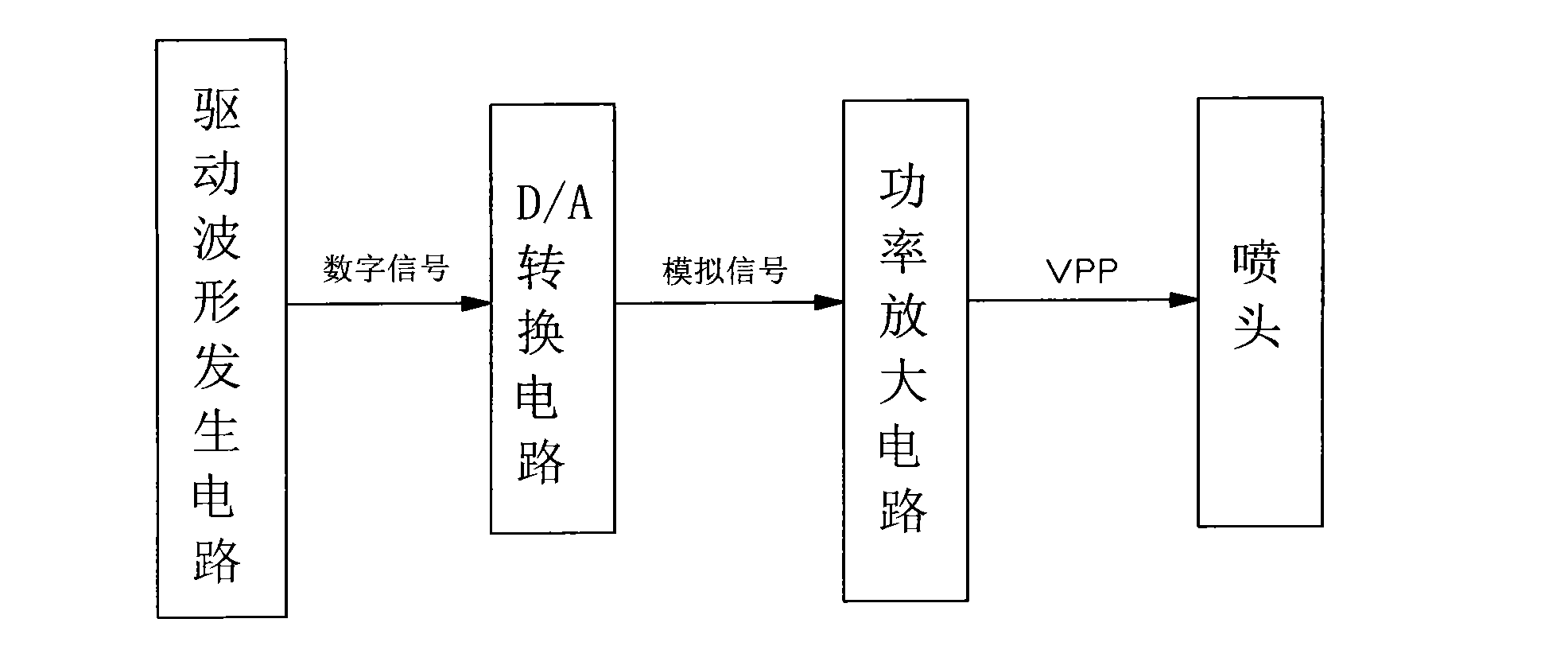
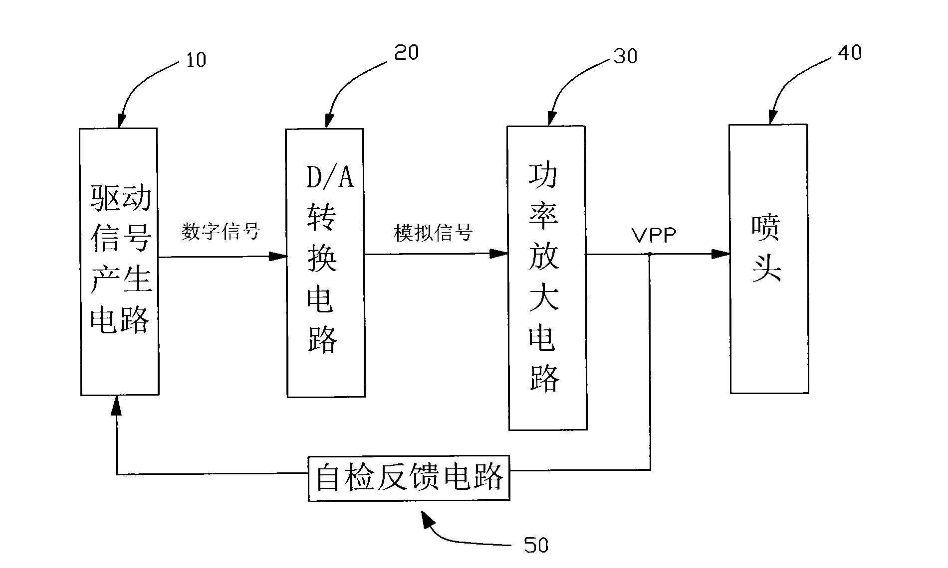
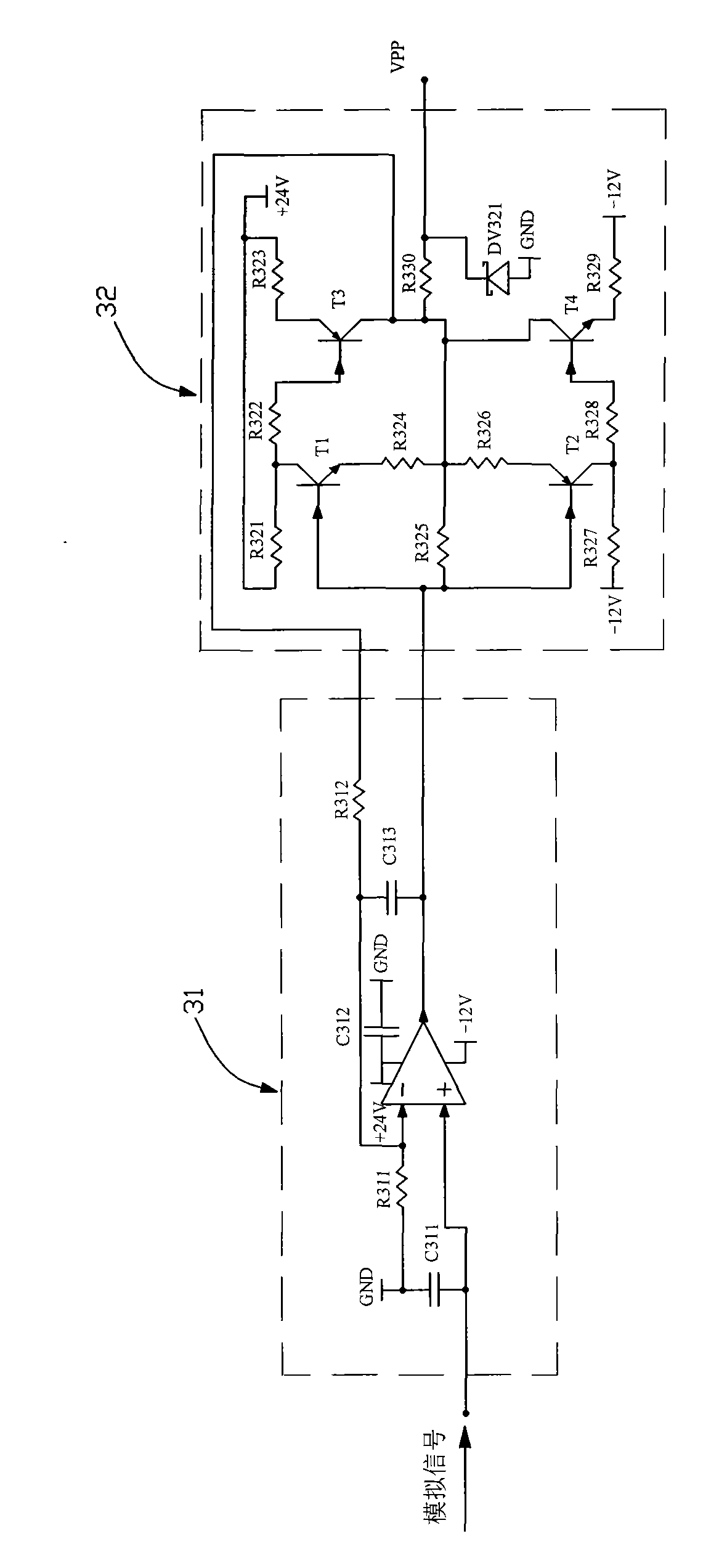
[0018] figure 2 It is a block diagram of the nozzle drive circuit for inkjet printers in the present invention, and the drive voltage signal is output from the drive signal generation circuit 10. The signal is a digital signal, which is converted into an analog signal by a D / A conversion circuit 20, and the analog signal Amplified by the power amplifying circuit 30, the amplified driving voltage is used to drive the nozzle for printing. image 3 It is a circuit diagram of the power amplifier circuit 30. The power amplifier circuit 30 includes an amplifier circuit 31 and a push-pull circuit 32. The analog signal output from the D / A conversion circuit 20 first enters the amplifier circuit 31. This amplifier circuit 31 is a voltage negative feedback ratio The operational amplifier circuit determines the magnification fac...


PUM


Abstract

The invention discloses a nozzle driving circuit for inkjet printers, comprising a drive signal generating circuit, a D/A (Digital/Analogue) switching circuit, a power amplifying circuit and a self-check feedback circuit, wherein the drive signal generating circuit is used for outputting digital signals of a drive voltage; the D/A switching circuit is used for converting the digital signals of the drive voltage output by the drive signal generating circuit, into analogue signals; the power amplifying circuit is used for amplifying the analogue signals of the drive voltage subjected to the conversion of the D/A switching circuit; the self-check feedback circuit is used for checking whether a nozzle driving voltage is output in a preset linear mode or not after the amplification of the power amplifying circuit; and the amplified drive voltage is compared with a drive voltage obtained through theoretical calculation and the comparative result is fed back to the drive signal generating circuit to ensure that the output digital signals of the drive voltage can be adjusted according to the comparative result through the drive signal generating circuit. According to the invention, the signal error is reduced through carrying out self-check and feedback on the nozzle driving voltage, therefore, the printing quality of the inkjet printers is improved.

Description

technical field [0001] The invention relates to a nozzle drive circuit for an inkjet printer. Background technique [0002] An inkjet printer draws set characters and images by ejecting tiny ink droplets of one or more color inks from multiple nozzles and forming the fine particles on the printing medium. Gradation refers to the density state of each color included in the pixel represented by the ink dot, and the number of ink dots representing the gray scale is called the number of gray scales. In order to change the gradation, it is necessary to change the driving pulse for the actuator provided in the inkjet head. For example, when the actuator is a piezoelectric element, if the voltage value applied to the piezoelectric element is increased, the change amount of the piezoelectric element increases. Therefore, this method can be used to change the gradation of ink dots. By combining and connecting a plurality of drive pulses with different voltage wave heights, a drive ...

Claims


Application Information

Patent Timeline
Patent Type & Authority Applications(China)
IPC IPC(8): B41J2/01B41J29/393
Inventor 张原
Owner BEIJING MEIKEYI
Why Eureka
Try Eureka