Brake switch adjustment method

A switch adjustment and brake technology, which is applied in the direction of the hoisting device, etc., can solve the problems of elevator stop, elevator control influence, and no margin for action points.

Inactive Publication Date: 2014-10-15
TOSHIBA ELEVATOR KK
View PDF9 Cites 0 Cited by
  • Summary
  • Abstract
  • Description
  • Claims
  • Application Information

AI Technical Summary

Problems solved by technology

[0004] However, in the case of the above-mentioned brake device that mechanically closes or opens the brake switch, on the other hand, for example, when the open side is adjusted, the closed side is not adjusted.
Therefore, for example, it is possible to calculate the margin of the operating point on the closing side based on the full stroke (storoke) of the striker (striker), etc., but it is not guaranteed to be reliable, and it is also difficult to confirm.
[0005] In addition, when the operating point does not have a margin, for example, there may be a phenomenon that the brake switch does not turn off even if the brake is released.
When this phenomenon occurs, for example, it will also affect the overall control of the elevator, and it may also be judged that the elevator stops due to a fault.

Method used


Image

  • Brake switch adjustment method
  • Brake switch adjustment method
  • Brake switch adjustment method

Examples


no. 1 approach

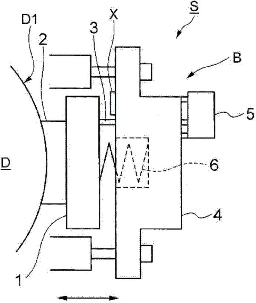
[0033] figure 1 It is a schematic diagram showing the overall configuration of the brake device S (released state) according to the first embodiment of the present invention. The brake device S is a device for stopping the operation of the hoisting machine. Although both illustrations are omitted, the hoist has a main sheave around which a rope is wound, and the main sheave is connected to a motor to be rotationally driven. Driven by the rotation of the main sheave, the car and the counterweight connected to the two ends of the rope travel in opposite directions in the hoistway.

[0034] The brake device S includes a drum D and a brake main body B. As shown in FIG. The drum D is formed in a cylindrical shape concentric with a main sheave (not shown), and is connected to the main sheave. Therefore, when the motor is driven, the drum D rotates along with the rotation of the main sheave.

[0035] The brake main body B is provided with an armature 1, a brake shoe 2, a striker ...


PUM


Abstract

The invention provides an adjusting method for a brake switch, and the method comprises steps of: pressing a boot (2) onto a reel (D) to release a brake; fastening a controller switch adjustment bolt (5g), which performs motion adjustment of a controller switch, the controller switch is in a contact with an impactor (3) via a coil housing (4), and performs switch of attraction and release of the brake (5) through close and disconnection of the switch; loosening the adjustment bolt (5g) to a motion point of disconnection of the switch (5); loosening the adjustment bolt (5g) to make the switch (5) further move to a specified position from the position of the motion point of disconnection of the switch (5); and under the condition of normal motion, inputting a gasket (X) between an armature (1) and a coil housing (4).

Description

technical field [0001] Embodiments of the present invention relate to a brake switch adjustment method for controlling the operation of an elevator. Background technique [0002] When controlling the operation of an elevator, one of the most important controls is brake control for stopping the elevator (car). This brake control is directly related to the safety of the passengers in the car. Here, as in the invention of Japanese Laid-Open Patent Publication No. 11-265963 (Patent No. 4295373) (hereinafter referred to as Patent Document 1), a monitoring system for monitoring a brake control device using an electronic component (component) is disclosed. device. [0003] Furthermore, in the case of a brake device in which the brake switch is mechanically turned on or off, how to adjust the brake switch becomes a problem. In this case, either one of the closing side and the opening side is often adjusted so that the operating point has a certain margin. [0004] However, in th...

Claims


Application Information

Patent Timeline
Patent Type & Authority Patents(China)
IPC IPC(8): B66D5/30B66D5/08
Inventor 小川哲
Owner TOSHIBA ELEVATOR KK
Why Eureka
Try Eureka