
All-bolt connection node structure of H-shaped steel beam and H-shaped steel column

A joint structure, H-beam technology, applied in building construction, construction, etc., can solve the problems of increasing component cycle, high welder level requirements, beam brittle fracture, etc., to enhance fatigue resistance and seismic performance, reduce welding residual stress. , Improve the effect of fatigue resistance

Inactive Publication Date: 2012-09-05
MAGANG (GROUP) HOLDING CO LTD +1
View PDF6 Cites 1 Cited by
  • Summary
  • Abstract
  • Description
  • Claims
  • Application Information

AI Technical Summary

Problems solved by technology

For the processing of this node, there are the following quality defects and potential safety hazards: ①Because the components have short beams or corbels, the components are often large in size, and the welding is affected by wind, weather temperature and humidity, which requires high requirements for the production site; Large-area manual electric welding operation, low degree of mechanization, high labor cost
② When welding short cantilever beams or corbel flange plates to columns, if flat welding is used, the column needs to be turned over many times, and appropriate supports must be set up, which is labor-intensive and time-consuming, and there are many safety hazards; if vertical welding is used, The requirements for welders are high, and the welding quality of the flange plate and the column is difficult to meet the requirements of the first-class weld seam
⑤The end of the beam or corbel should be equipped with a process hole. Due to the existence of the process hole, brittle fracture of the beam starting from the process hole is easy to occur
⑥ After the assembly and welding of the components are completed, they must go through the flaw detection and correction of the weld seam, which is not conducive to the flow operation of the components, which increases the cycle of component production

Method used


Image

  • All-bolt connection node structure of H-shaped steel beam and H-shaped steel column
  • All-bolt connection node structure of H-shaped steel beam and H-shaped steel column
  • All-bolt connection node structure of H-shaped steel beam and H-shaped steel column

Examples


Embodiment Construction

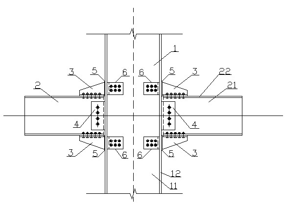
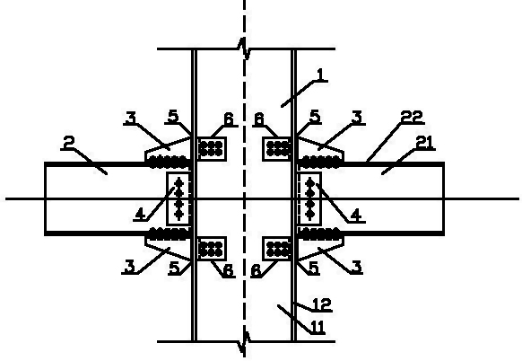
[0010] The full-bolt connection node structure of H-shaped steel beams and H-shaped steel columns in the present invention includes solid-web H-shaped steel columns 1 and H-shaped steel short beams 2 that are vertically connected to each other, and the solid-web H-shaped steel column 1 includes column webs 11 and vertical The column flange 12 connected on both sides of the column web 11, the H-shaped steel short beam 2 includes the beam web 21 and the beam flange 22 vertically connected on both sides of the beam web 21, and it also includes a special-shaped support plate 3 and a shear plate 4 , the special-shaped supporting plate 3 and the shear plate 4 make the H-shaped steel short beam 2 connected to the two outer sides of the column flange 12 of the solid-web type H-shaped steel column 1 .

[0011] Among them, there are eight special-shaped supporting plates 3, which are respectively arranged at eight right angles formed by the outer side of the column flange 12 and the oute...


PUM


Abstract

The invention discloses an all-bolt connection node structure of an H-shaped steel beam and an H-shaped steel column. The structure comprises a solid-web H-shaped steel column and an H-shaped steel short beam in vertical connection with each other; the solid-web H-shaped steel column comprises a column web and column flanges vertically connected on the two sides of the column web; the H-shaped steel short beam comprises a beam web and beam flanges vertically connected on the two sides of the beam web; the structure is characterized by also comprising a special-shape support plate and an anti-shearing plate; and the special-shape support plate and the anti-shearing plate enable the H-shaped steel short beam to be connected on the two outer sides of the column flanges of the solid-web H-shaped steel column. In the all-bolt connection node structure disclose by the invention, the anti-fatigue performance and seismic performance of the node are improved and the external force transfer and internal force transfer are organically combined without weakening the strength of the H-shaped steel column.

Description

technical field [0001] The invention relates to a connection structure between an H-shaped steel beam and an H-shaped steel column, belonging to the construction field. Background technique [0002] At present, the standard form of joints of H-shaped steel beams and H-shaped steel columns in domestic steel structures is usually fully welded joints or modified on fully welded joints (H-shaped cantilevered short beams and H-shaped steel columns are fully welded). Gas welding and semi-automatic cutting machines are usually used to process the end bevel and process hole (lock) of H corbels and beams in the workshop, and an arc strike plate is added at the end to ensure the welding quality during welding. For the processing of this node, there are the following quality defects and potential safety hazards: ①Because the components have short beams or corbels, the components are often large in size, and the welding is affected by wind, weather temperature and humidity, which requir...

Claims


Application Information

Patent Timeline
Patent Type & Authority Applications(China)
IPC IPC(8): E04B1/58
Inventor 刘家彪
Owner MAGANG (GROUP) HOLDING CO LTD
Learn More