Test table for five-function test of driving shaft assembly of constant velocity universal joint

A constant velocity universal joint and functional testing technology, applied in the direction of machine gear/transmission mechanism testing, etc., can solve problems such as affecting the testing accuracy, stepping motor out of step, no explanation, etc., to achieve a wide range of applications, unified testing benchmarks, Measure accurate effects

Inactive Publication Date: 2012-09-05
SHANGHAI JIAO TONG UNIV
View PDF3 Cites 36 Cited by
  • Summary
  • Abstract
  • Description
  • Claims
  • Application Information

AI Technical Summary

Problems solved by technology

Among them: 1 Regarding the swing angle test, this article only discusses the test method on the swing angle of the fixed end and the sliding end of the assembly, but does not explain the conditions under which the project is tested and the relationship between the project and the swing torque , because no matter what the test is, it must be carried out under certain conditions, and there is a certain correspondence between the swing angle and the swing torque; The magnitude of the measured force is multiplied by the distance from the tension sensor to the swing center to obtain the swing torque value. This test method is an indirect measurement, which is not as accurate as the direct test. At the same time, the test of this project also does not indicate the condition of the swing angle. 3. For the test of the displacement of the sliding end, the paper uses a stepping motor to drive the screw to rotate, then the nut linearly moves to drive the movable headstock to move on the linear guide rail, and the chuck drives the drive shaft to slide The end moves in a straight line, and the displacement is measured by the line...

Method used


Image

  • Test table for five-function test of driving shaft assembly of constant velocity universal joint
  • Test table for five-function test of driving shaft assembly of constant velocity universal joint
  • Test table for five-function test of driving shaft assembly of constant velocity universal joint

Examples


Embodiment Construction

[0033] Below in conjunction with accompanying drawing, the embodiment of the present invention is described in detail: present embodiment is carried out on the premise of technical solution of the invention, has provided detailed embodiment and specific operation process, but protection scope of the present invention is not limited to following implementation example.

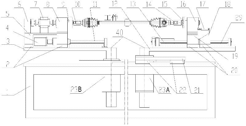
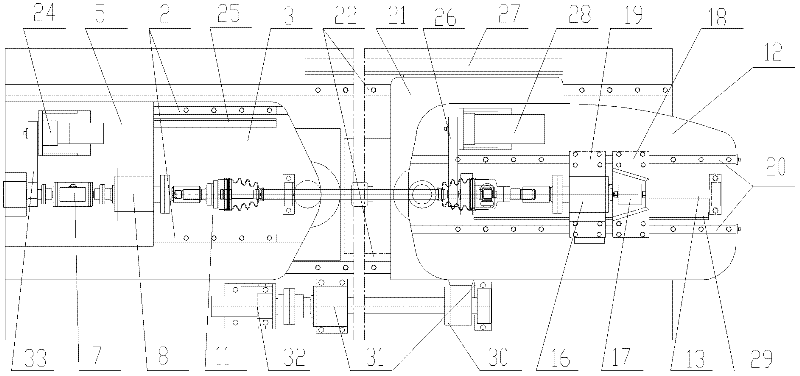
[0034] Such as figure 1 , 2 As shown, this embodiment includes: frame 1, fixed end guide rail and slider 2, fixed end swing table 3, fixed end linear displacement drive assembly 4, fixed end sliding table 5, fixed end rear support seat 6, torque Speed ​​sensor 7, main shaft support seat 8, main shaft 9, fixed end fixture 10, fixed end screw nut 11, sliding end swing platen 12, sliding end screw nut 13, sliding end fixture 14, sliding end shaft 15, sliding end support seat 16, pull pressure sensor 17, rear sliding plate 18, front sliding plate 19, sliding end guide rail and slider 20, large sliding table plate...


PUM


Abstract

The invention relates to a test table for a five-function test of a driving shaft assembly of a constant velocity universal joint. The test table comprises a rack, a fixing end and a slippage end, wherein the fixing end and the slippage end are located on the rack; the fixing end comprises a guide rail and a sliding block, a swinging bedplate, a linear displacement driving assembly, a sliding bedplate, a torque rotating speed sensor, a spindle supporting base, a spindle, a clamp, a swinging and driving assembly, a spindle driving assembly, a linear displacement sensor and the like; the slippage end comprises a swinging bedplate, a clamp, a rotating shaft, a supporting base, a pull pressure sensor, a rear sliding board, a front sliding board, a guide rail and a sliding block, a swinging and driving assembly, a linear displacement sensor and the like; and the rack comprises a guide rail and a sliding block, a linear displacement sensor, a linear displacement driving assembly and the like. With regard to the driving shaft assemblies of the constant velocity universal joint with the different structures and sizes of the working pieces, the test table can test working pieces with various specifications and structures by replacing the clamps, and adjusting the position of the clamp at the fixing end and the position of the clamp at the slippage end, and the size of a rotary center distance.

Description

technical field [0001] The invention relates to a mechanism in the technical field of testing components of constant velocity universal joint drive shaft assemblies for automobiles, in particular to a five-function test bench for constant velocity universal joint drive shafts. Background technique [0002] In the vehicle drive system, the constant velocity universal joint drive shaft assembly is the only important component that transmits the power output from the gearbox to the wheels. It is mainly composed of three parts: the fixed end universal joint, the mandrel, and the moving end universal joint. In addition to the clearance, the assembly has displacement and swing angle, starting torque, dynamic and static sliding force, fixed end swing torque and swing angle, and sliding end swing torque and swing angle. These characteristics are also used to evaluate product design, manufacturing and assembly quality. Key indicators. At present, due to the test and research of con...

Claims


Application Information

Patent Timeline
IPC IPC(8): G01M13/02
Inventor 郭常宁杨洪兴
Owner SHANGHAI JIAO TONG UNIV
Why Eureka
Try Eureka