Cylindrical structure and method of production thereof

A structure and cylinder technology, applied in the field of propulsion devices, can solve problems such as damage

CN102656004AInactive Publication Date: 2012-09-05IHI CORP +1
6 Cites 4 Cited by

Patent Information

Authority / Receiving Office
CN · China
Patent Type
Applications(China)
Current Assignee / Owner
Publication Date
2012-09-05
Estimated Expiration
Not applicable · inactive patent

Smart Images

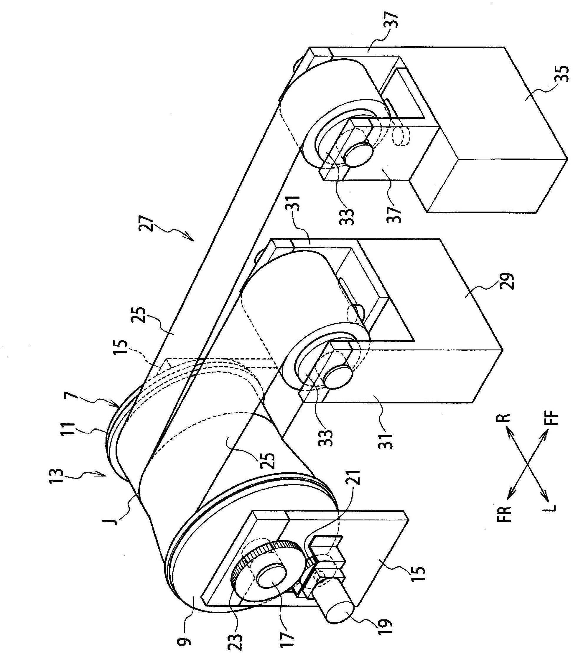
  • Figure 1
    Figure 1
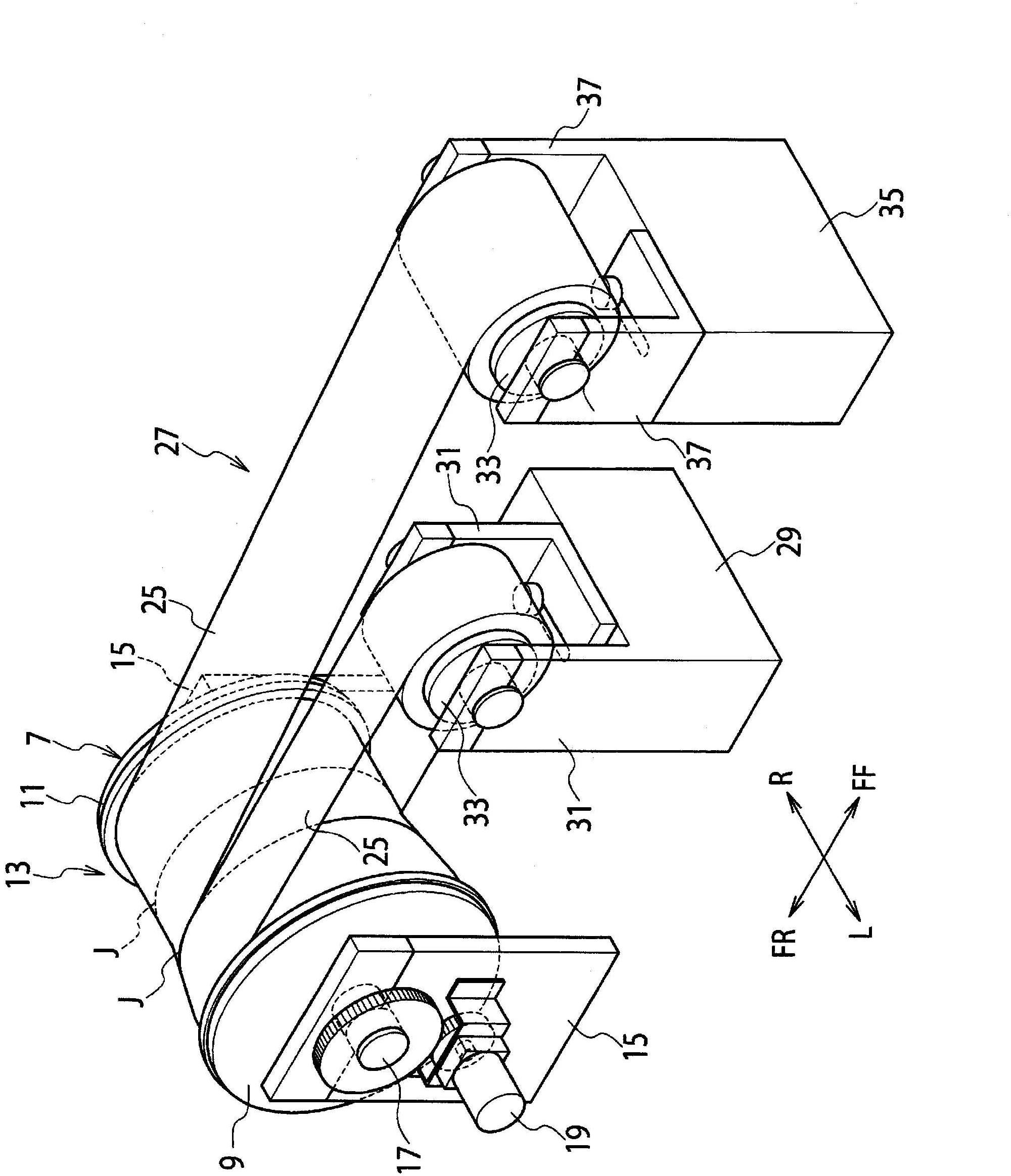
  • Figure 2
    Figure 2
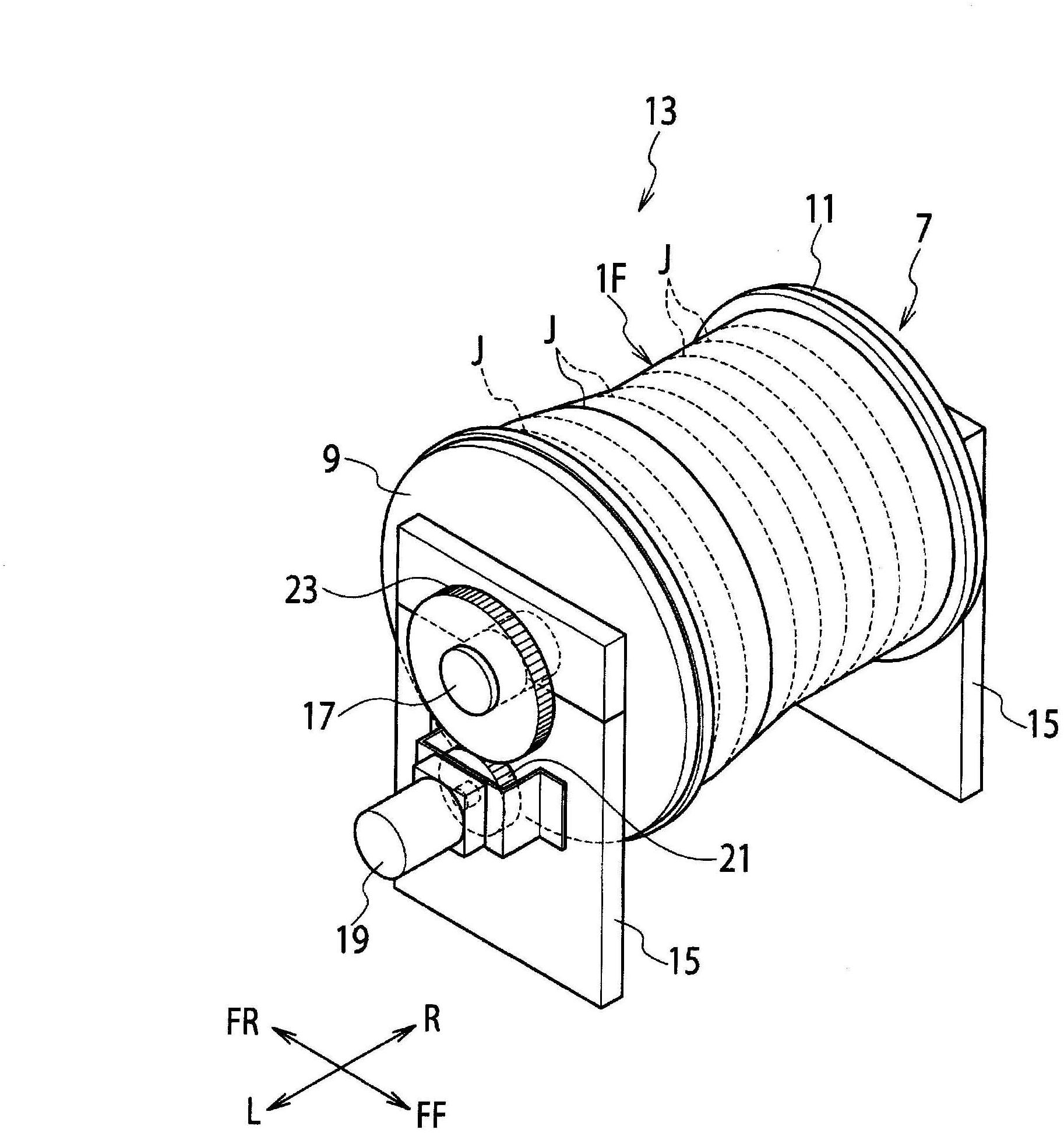
  • Figure 3
    Figure 3
Patent Text Reader

Abstract

The disclosed method for production of a cylindrical structure having an axis direction comprises winding a first layer containing plural textile layers composed respectively of reinforced fibers around a mandrel to form a first join line by contact of the edges thereof extending in the circumferential direction; winding a second layer containing plural textile layers composed respectively of the reinforced fibers around the first layer to form a second join line by contact of the edges thereof extending in the circumferential direction with the second join line shifted from the first join line in the axis direction; winding a third layer containing plural textile layers composed respectively of the reinforced fibers around the second layer to form a third join line by contact of the edges thereof extending in the circumferential direction with the third join line shifted from both of the first join line and the second join line in the axis direction; and bonding the layers together with a resin.
Need to check novelty before this filing date? Find Prior Art

Description

technical field

[0001] The present invention relates to a propulsion device in the field of aerospace, and in particular to a cylindrical structure made of fiber-reinforced plastic such as a fan cover of a jet engine and a motor cover of a rocket engine, and a manufacturing method thereof. Background technique

[0002] Regarding the jet engine of an aircraft, as an example, external air is sucked in by a fan, compressed by a compressor, and used for combustion of fuel in a combustor. After part of the generated energy is extracted by the turbine, the combustion gas is discharged rearward from the nozzle at the rear of the engine. The entirety of a jet engine is generally surrounded and supported by an aerodynamically designed casing called the nacelle. The nacelle as a whole is very large, and required characteristics such as strength vary depending on the location of the nacelle, so the nacelle is typically manufactured by dividing it into a plurality of cowling parts such...

Examples

Embodiment Construction

[0017] Hereinafter, embodiments of the present invention will be described with reference to the drawings.

[0018] For ease of description, the directions shown as L and R in the accompanying drawings are respectively expressed as left and right, and the directions shown as FR and FF are respectively expressed as backward and forward, but these expressions are non-limiting for the present invention of.

[0019] The manufacturing method of this embodiment can be applied as an example in Figure 7 Manufacture of fan shrouds for jet engines of aircraft shown in . The engine 3 generally includes an engine main body and an engine nacelle surrounding and supporting the engine main body, and the engine main body includes a fan 5 . The nacelle includes a plurality of cowling components, each cowling component being substantially symmetrical about an axis. Among the cowl parts, the part surrounding the fan 5 is the fan cover 1 . The fan cover 1 has a substantially cylindrical shap...