
Novel apparatus for solid particle falling

A technology of solid particles and shedding, applied in large containers, containers, loading/unloading, etc., which can solve the problems of troublesome handling and single driving method.

Inactive Publication Date: 2012-09-12
黄建
View PDF14 Cites 8 Cited by
  • Summary
  • Abstract
  • Description
  • Claims
  • Application Information

AI Technical Summary

Problems solved by technology

[0002] At present, such solid particle shatters sold on the market are troublesome to deal with and have a single driving method when they fail.

Method used


Image

  • Novel apparatus for solid particle falling
  • Novel apparatus for solid particle falling
  • Novel apparatus for solid particle falling

Examples


Embodiment Construction

[0023] The present invention will be described in further detail below in conjunction with the accompanying drawings and specific embodiments.

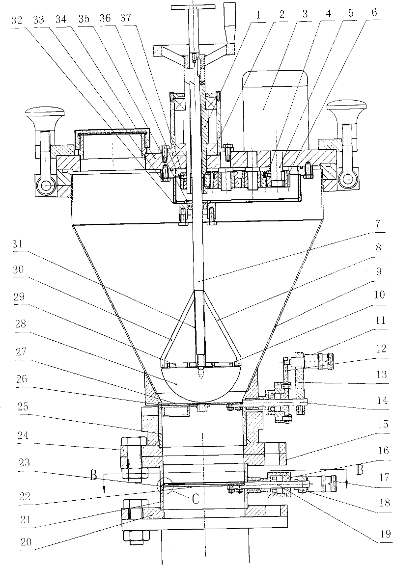
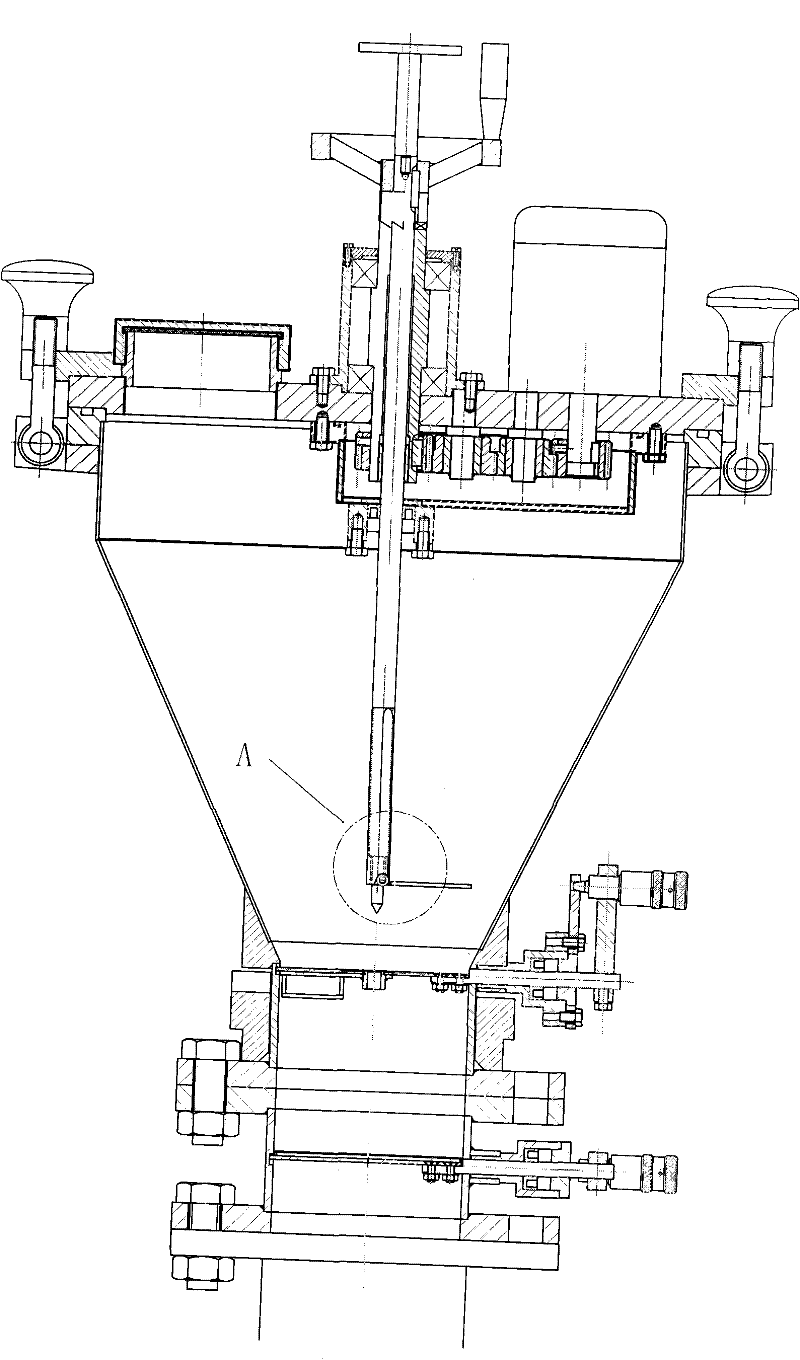
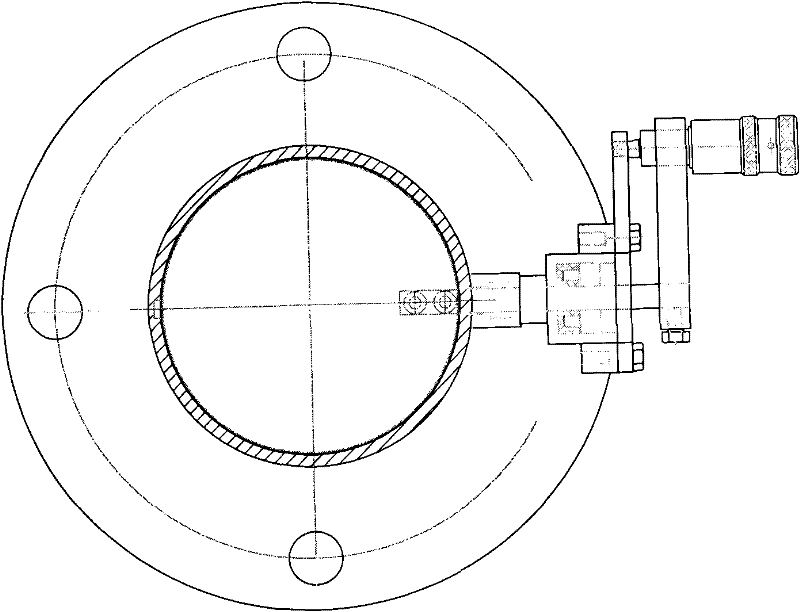
[0024] figure 1 , figure 2 , image 3 , Figure 4 , Figure 5 , Figure 6 , Figure 7 , Figure 8 , Figure 9 Described is a new type of solid particle shaker. There is a vertical stirring shaft 7 in the center of the rounded truss-shaped particle container 9 of the new particle shatter, which is installed in the shaft sleeve 1 on the container cover 34, and it is in motion with the shaft sleeve 1, and can move up and down in the shaft sleeve 1 and turn. A stirring head is installed on the lower end of the vertical stirring shaft 7, and its shape is a part of the envelope of the right cone, namely, the central axis pipe 31 of the stirring head is respectively welded with an equal regular triangle frame 8,30, with two triangular frames The base 10,29 of the bottom edge is connected as a shaft with a rotatable semicircular hi...


PUM


Abstract

The invention provides a novel apparatus for solid particle falling. A vertical mixing shaft is arranged in the center of an inverted frustum shaped container of the apparatus, the vertical mixing shaft is mounted in a shaft sleeve, and the shaft sleeve is mounted in a bearing pedestal on a container cover. The vertical mixing shaft can be moved up and down and rotated in the shaft sleeve. A mixing head is arranged at the lower end of the mixing shaft, and the shape of the mixing head is a portion enveloped by a right circular cone. A gear is arranged at the lower portion of the shaft sleeve, and the gear forms a transmission pair with the gear on a motor shaft. A clutch located between the mixing shaft and the shaft sleeve is disengaged , and the rotation of the mixing shaft is driven by a motor. The clutch is engaged, and the rotation of the mixing shaft can be driven manually. Two bottom portions which are overlapped to each other are arranged at a small end of the material container. The upper bottom portion is integral with the container, and a movable circular multilayer sheet component is arranged inside the upper bottom portion. The normal operating condition is a horizontal condition. The multilayer sheet can be rotated about a horizontal axis. The lower bottom portion is a completely independent bottom portion. A movable circular bilayer sheet which is closed or opened is arranged inside of the lower bottom portion. The circular bilayer sheet consists of a cover and a bottom sheet. A vibration sensor or a sound sensor or a pressure sensor is arranged inside of the circular bilayer sheet.

Description

technical field [0001] The invention relates to a novel solid particle shatter. Background technique [0002] At present, such solid particle shatters sold on the market are troublesome to deal with and have a single driving mode when a failure occurs. Contents of the invention [0003] The purpose of the present invention is to provide novel solid particle shatter, and this novel solid particle shatter has following characteristics; [0004] 1 new style stirring head. [0005] 2 double gearing. [0006] 3 Double insulated bottom. [0007] 4 Falling particle amount detection parts. [0008] The object of the present invention is achieved like this: there is a vertical stirring shaft in the center of the rounded truncated truncated particle container of the novel solid particle shatter, which is installed in the shaft sleeve on the container cover, and it is movably matched with the shaft sleeve. The sleeve lifts up and down and rotates. A new type of stirring head is...

Claims


Application Information

Patent Timeline
IPC IPC(8): B65D83/06B65D88/54B65G65/40B65G65/48
Inventor 黄建
Owner 黄建
Learn More