Method for wet mixing cementitious slurry for fiber-reinforced structural cement panels

一种水泥板、浆液的技术,应用在化学仪器和方法、混合机、水泥搅拌装置等方向,能够解决混合器堵塞、生产中断等问题

Inactive Publication Date: 2009-11-04
USG CORP
View PDF20 Cites 5 Cited by
  • Summary
  • Abstract
  • Description
  • Claims
  • Application Information

AI Technical Summary

Problems solved by technology

[0020] However, traditional mixers tend to clog causing production interruptions

Method used


Image

  • Method for wet mixing cementitious slurry for fiber-reinforced structural cement panels
  • Method for wet mixing cementitious slurry for fiber-reinforced structural cement panels
  • Method for wet mixing cementitious slurry for fiber-reinforced structural cement panels

Examples


no. 2 Embodiment

[0146] Introducing the volume percent of loose fibers uniformly distributed in the slurry 46 is an important factor in achieving the desired board strength. Therefore, the addition of these fibers is required to increase efficiency. Believe figure 1 The system shown required in some cases an excessive amount of slurry layer to obtain an SCP panel with a sufficient fiber volume percentage.

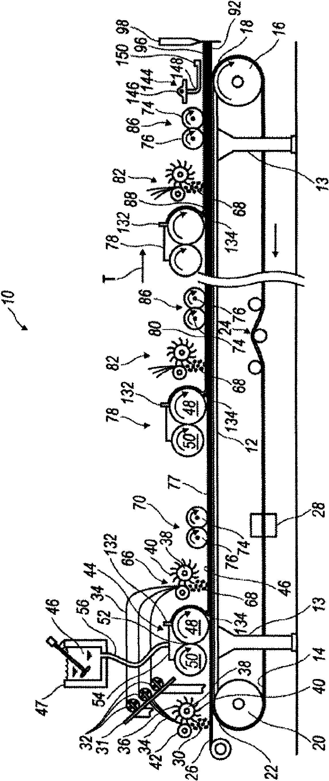
[0147] Therefore, in order to manufacture high-performance, fiber-reinforced SCP panels with relatively large amounts of fibers added to each slurry layer, the Image 6 An alternative SCP board production line or system is shown in and generally indicated at 130 . In many cases, it is possible to obtain an increased content of fibers in each board with this system. Although figure 1 discloses the deposition of a single independent fiber layer in each of the next individual slurry layers deposited after the initial layer, however, the production line 130 includes the accumulation of mu...

example 1

[0242] see figure 1 c, Fragment of SCP panel 92 made of fibers and slurry. The cement portion of the slurry consisted of 65 wt.% calcium sulfate alpha hemihydrate, 22 wt.% type III ordinary Portland cement, 12 wt.% silica fume and 1 wt.% slaked lime. The liquid portion of the slurry included 99.19 wt.% water and 0.81 wt.% ADVACAST superplasticizer manufactured by W.R. Grace and Co. The liquid:cement weight ratio was 0.55 and the aggregate (EXTENDOSPHERES SG microspheres):cement weight ratio was 0.445.

[0243] Using the present system, a slurry is produced according to the current process, with four slurry layers 77, 80, 88 and 90 as shown. Such a board should be considered merely illustrative, as a board 92 made according to the present system may have one or more layers. By using the above mathematical relationship, the size layers 77, 80, 88 and 90 can have different fiber volume percentages. For example, the skin or facing 77, 90 has a specified fiber volume fraction ...

example 2

[0249] The residence time of the wet slurry in the vertical mixing chamber in the different examples was experimentally determined by determining the residence time of the red dyed tracer added to the slurry before the slurry was completely drained from the vertical mixing chamber. Multiple tests were performed to determine residence time in the vertical mixing chamber using a red dyed tracer added to the water and powder slurries upon entry into the vertical mixing chamber. The composition of the cement slurry is about the same as the above-mentioned composition of Example 1.

[0250] The equipment used was a digital scale to weigh the slurry, a barrel to collect the slurry, a stop watch to measure the elapsed time at different points. The mixer was used with three different mixing chamber designs listed in Tables 2-4, namely a 12 inch mixer, an 8 inch extended mixer (Extended Mixer), and an 8 inch stock mixer (Stock Mixer).

[0251] The 8-inch common mixer is the DUO MIX 20...


PUM

PropertyMeasurementUnit
flexural strengthaaaaaaaaaa

Abstract

The present invention discloses a process employing a wet mixer having a vertical mixing chamber for forming a wet slurry of a cementitious powder and liquid. The vertical mixing chamber is designed to provide the required amount of mixing to provide thoroughly mixed, uniformly thin slurry within a mixing residence time that allows for adequate supply of slurry to ensure continuous operation of an associated cement panel production line. Gravity feed means for supply of cementitious powder and water to the slurry mixing area of the chamber is also disclosed.

Description

[0001] Cross References to Related Applications [0002] This application claims priority from US Patent Application Serial No. 11 / 555,655, filed November 1, 2006, the entirety of which is incorporated herein by reference. [0003] This application is related to the following co-pending patent applications: [0004] U.S. Patent Application No. 11 / 555,647 (Attorney Docket No. APV31960 / 3991), entitled PROCESS AND APPARTUS FOR FEEDING CEMENTITIOUSSLURRY FOR FIBER-REINFORCED STRUCTURAL CEMENT PANELS, filed on November 1, 2006; [0005] U.S. Patent Application No. 11 / 555,658 (Attorney Docket No. APV31963 / 3994), entitled APPARTUS AND METORD FOR WET MIXING CEMENTITIOUSSLURRY FOR FIBER-REINFORCED STRUCTURAL CEMENT PANELS, filed November 1, 2006; [0006] U.S. Patent Application No. 11 / 555,661 (Attorney Docket No. APV31964 / 3995), entitled PANEL SMOOTHING PROCESS AND APPARTUS FOR FORMINGA SMOOTH CONTINUOUS SURFACE ON FIBER-REINFORCEDSTRUCTURAL CEMENT PANELS, filed on November 1, 2006; ...

Claims


Application Information

Patent Timeline
Patent Type & Authority Applications(China)
IPC IPC(8): B32B13/00B01F27/96
CPCB28C7/0418C04B40/0028B01F7/022B01F3/1221B01F15/0251B28C5/1284C04B28/14B01F13/1027B28B19/0092B01F7/32B01F7/04Y02W30/91B01F23/53B01F27/62B01F27/70B01F27/96B01F33/821B01F35/71775C04B7/02C04B14/185C04B14/24C04B14/301C04B18/082C04B20/0048C04B22/064C04B40/02
Inventor 劳埃德·M·乔治阿希什·迪贝尤金·斯科特·斯蒂文德
Owner USG CORP
Why Eureka
Try Eureka