Lenticular lens grating, liquid crystal grating and display device

A cylindrical lens grating and display device technology, applied in the field of 3D display, can solve problems such as affecting the display effect, and achieve the effects of reducing the difficulty of process development, improving the 3D display effect, and improving the product yield.

Active Publication Date: 2012-09-12
BOE TECH GRP CO LTD
View PDF11 Cites 32 Cited by
  • Summary
  • Abstract
  • Description
  • Claims
  • Application Information

AI Technical Summary

Problems solved by technology

[0007] Aiming at the shortcomings of the prior art, the present invention provides a cylindrical lens grating, a liquid crystal grating and a display device in order to solve the p

Method used


Image

  • Lenticular lens grating, liquid crystal grating and display device
  • Lenticular lens grating, liquid crystal grating and display device
  • Lenticular lens grating, liquid crystal grating and display device

Examples


Embodiment 1

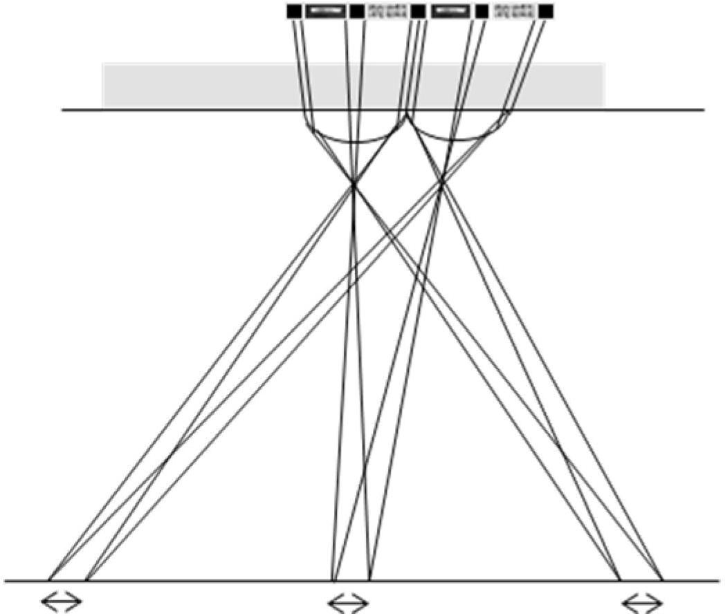
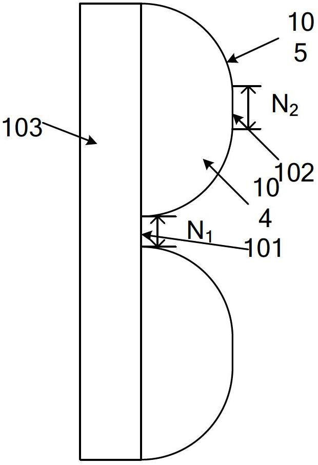
[0049]Fig. 2 is the partially enlarged view of the section of the cylindrical lens grating of the present invention, in the embodiment 1 of Fig. 2 (a), in order to suppress the enlargement effect of the convex lens effect to the black matrix, the cylindrical lens grating of the present invention changes the prior art The cylindrical lens is closely arranged, and the cylindrical lens grating also includes the central axis of the cylindrical lens (referring to the straight line connecting the focal points on both sides of the lens, usually located in the middle of the lens, and the light passing through the lens in this direction will not be deflected ) multiple planar sections perpendicular to each other. Specifically, a plurality of convex cylindrical lenses 104 are arranged in parallel and formed on the substrate 103, wherein every two cylindrical lenses 104 are separated by a first plane 101, the first plane 101 is perpendicular to the central axis of the cylindrical lens, an...

Embodiment 2

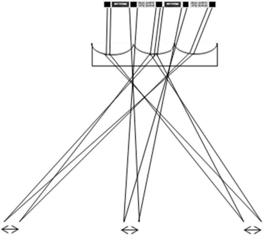
[0051] FIG. 2( a ) uses a convex lens as an example for illustration, and Embodiment 2 of FIG. 2( b ) further demonstrates the embodiment of the present invention in which a concave lens is used to form a cylindrical lens grating. In the second embodiment, a plurality of concave cylindrical lenses 104' are arranged in parallel on the substrate 103, and the concave cylindrical lens grating also includes a plurality of planar parts perpendicular to the central axis of the cylindrical lenses 104', wherein each two The two concave cylindrical lenses 104' are separated by a first plane 101, the first plane 101 is perpendicular to the central axis of the cylindrical lens, and the width of the first plane 101 is N 1 Or, the middle part of the upper surface 105' of each concave cylindrical lens 104' is formed with a second plane 102, and the second plane 102 is perpendicular to the central axis of the concave cylindrical lens 104' and is symmetrical with the central axis of the cylindr...

Embodiment 3

[0057] Figure 6 Embodiment 3 also discloses the implementation of the liquid crystal grating. In the liquid crystal grating, the degree of deflection of the liquid crystal molecules in each region is controlled mainly by applying a voltage to the electrodes on the inner surfaces of the substrates on both sides of the liquid crystal layer, thereby forming equivalently in the liquid crystal layer The processing effect of the cylindrical lens grating and the first plane on the light causes the light to have different deflection directions when passing through various regions of the liquid crystal layer.

[0058] Specifically, in Figure 6 In Embodiment 3, the liquid crystal grating includes an upper substrate 106, a lower substrate 107, and a liquid crystal layer 108 disposed between the upper substrate and the lower substrate. In addition, a first electrode layer 109 is disposed on the inner surface of the upper substrate 106. In the The inner surface of the lower substrate 10...


PUM


Abstract

The invention relates to the technical field of 3D (three-dimensional) display, and provides a lenticular lens grating, a liquid crystal grating and a display device. The lenticular lens grating comprises a plurality of lenticular lenses arrayed in parallel, wherein an interval part is arranged between at least two adjacent lenticular lenses, and is a first plane vertical to a central shaft of the lenticular lenses; and/or the middle part of an upper surface of at least one lenticular lens is a second plane which is vertical to a central shaft of the lenticular lens and is symmetrical with the central shaft of the lenticular lens as a symmetrical axis According to the invention, the structure of the lenticular lens grating is improved, so that a black matrix figure on a color filter cannot be refracted by the lenticular lenses so as to deformed, the phenomenon of moire effect is inhibited effectively, and the 3D display effect is obviously improved. In addition, the invention further discloses a manufacturing method of the lenticular lens grating, parameters of the grating can be flexibly adjusted according to structural characteristics and actual process of the display so as to achieve an ideal display effect, the development difficulty of the process is greatly reduced, the develop process is simplified, and the yield of products is improved.

Description

technical field [0001] The invention relates to the technical field of 3D display, in particular to a cylindrical lens grating, a liquid crystal grating and a display device. Background technique [0002] With the advancement of digital image processing technology and equipment manufacturing level, 3D display has become a popular trend in the display industry. The basic principle of the current 3D display is "parallax produces stereo", through certain facilities or technologies, the viewer can see different images in both eyes, that is, the left eye only sees the left eye image, and the right eye only sees the right eye image, and the left eye only sees the right eye image. The eye diagram and the right eye diagram are taken from two angles of a certain space scene, and these two are called a stereo image pair; the human brain will fuse the two images seen by the two eyes to produce a 3D effect . [0003] Because the method of obtaining 3D display effects through 3D glasse...

Claims


Application Information

Patent Timeline
IPC IPC(8): G02B5/18G02B27/26G02F1/1343G02F1/1335G02B30/25G02B30/28
CPCG02B3/0006G02B3/14G02F1/133526G02B30/25G02B30/28G02B3/00G02F1/13
Inventor 魏伟武延兵
Owner BOE TECH GRP CO LTD
Why Eureka
Try Eureka