Lenticular lens grating, liquid crystal grating and display device
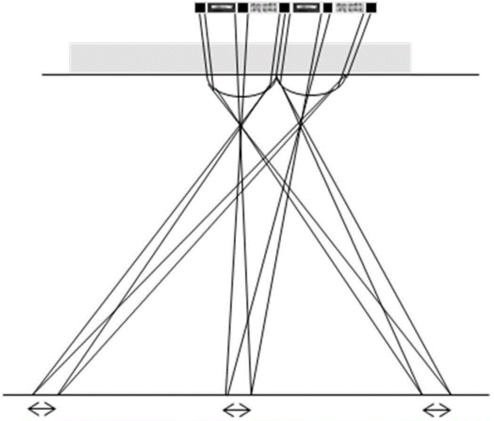
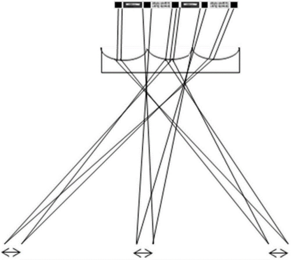
A technology of cylindrical lens grating and liquid crystal grating is applied in the field of 3D display, which can solve problems such as affecting the display effect, and achieve the effects of reducing the difficulty of process development, suppressing the moiré phenomenon, and improving product yield.
- Summary
- Abstract
- Description
- Claims
- Application Information
AI Technical Summary
Problems solved by technology
Method used
Image
Examples
Embodiment 1
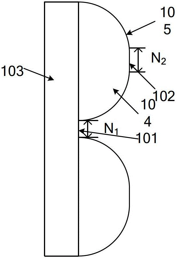
[0049]Fig. 2 is the partially enlarged view of the section of the cylindrical lens grating of the present invention, in the embodiment 1 of Fig. 2 (a), in order to suppress the enlargement effect of the convex lens effect to the black matrix, the cylindrical lens grating of the present invention changes the prior art The cylindrical lens is closely arranged, and the cylindrical lens grating also includes the central axis of the cylindrical lens (referring to the straight line connecting the focal points on both sides of the lens, usually located in the middle of the lens, and the light passing through the lens in this direction will not be deflected ) multiple planar sections perpendicular to each other. Specifically, a plurality of convex cylindrical lenses 104 are arranged in parallel and formed on the substrate 103, wherein every two cylindrical lenses 104 are separated by a first plane 101, the first plane 101 is perpendicular to the central axis of the cylindrical lens, an...
Embodiment 2
[0051] FIG. 2( a ) uses a convex lens as an example for illustration, and Embodiment 2 of FIG. 2( b ) further demonstrates the embodiment of the present invention in which a concave lens is used to form a cylindrical lens grating. In the second embodiment, a plurality of concave cylindrical lenses 104' are arranged in parallel on the substrate 103, and the concave cylindrical lens grating also includes a plurality of planar parts perpendicular to the central axis of the cylindrical lenses 104', wherein each two The two concave cylindrical lenses 104' are separated by a first plane 101, the first plane 101 is perpendicular to the central axis of the cylindrical lens, and the width of the first plane 101 is N 1 Or, the middle part of the upper surface 105' of each concave cylindrical lens 104' is formed with a second plane 102, and the second plane 102 is perpendicular to the central axis of the concave cylindrical lens 104' and is symmetrical with the central axis of the cylindr...
Embodiment 3
[0057] Figure 6 Embodiment 3 also discloses the implementation of the liquid crystal grating. In the liquid crystal grating, the degree of deflection of the liquid crystal molecules in each region is controlled mainly by applying a voltage to the electrodes on the inner surfaces of the substrates on both sides of the liquid crystal layer, thereby forming equivalently in the liquid crystal layer The processing effect of the cylindrical lens grating and the first plane on the light causes the light to have different deflection directions when passing through various regions of the liquid crystal layer.
[0058] Specifically, in Figure 6 In Embodiment 3, the liquid crystal grating includes an upper substrate 106, a lower substrate 107, and a liquid crystal layer 108 disposed between the upper substrate and the lower substrate. In addition, a first electrode layer 109 is disposed on the inner surface of the upper substrate 106. In the The inner surface of the lower substrate 10...
PUM
 Abstract
Description
Claims
Application Information
 - R&D
- Intellectual Property
- Life Sciences
- Materials
- Tech Scout
- Unparalleled Data Quality
- Higher Quality Content
- 60% Fewer Hallucinations
Browse by: Latest US Patents, China's latest patents, Technical Efficacy Thesaurus, Application Domain, Technology Topic, Popular Technical Reports.
© 2025 PatSnap. All rights reserved.Legal|Privacy policy|Modern Slavery Act Transparency Statement|Sitemap|About US| Contact US: help@patsnap.com


