
Filter element for an extractor hood and extractor hood

A filter element and fume extraction hood technology, applied in the field of fume extraction hoods, can solve the problems of increasing noise, increasing air resistance, etc., and achieve the effects of reducing flow resistance, improving odor elimination, and reducing volume flow

Active Publication Date: 2012-09-12
BOSCH SIEMENS HAUSGERATE GMBH
View PDF1 Cites 3 Cited by
  • Summary
  • Abstract
  • Description
  • Claims
  • Application Information

AI Technical Summary

Problems solved by technology

However this leads to increased air resistance which in turn produces increased noise generation

Method used


Image

  • Filter element for an extractor hood and extractor hood
  • Filter element for an extractor hood and extractor hood
  • Filter element for an extractor hood and extractor hood

Examples


Embodiment Construction

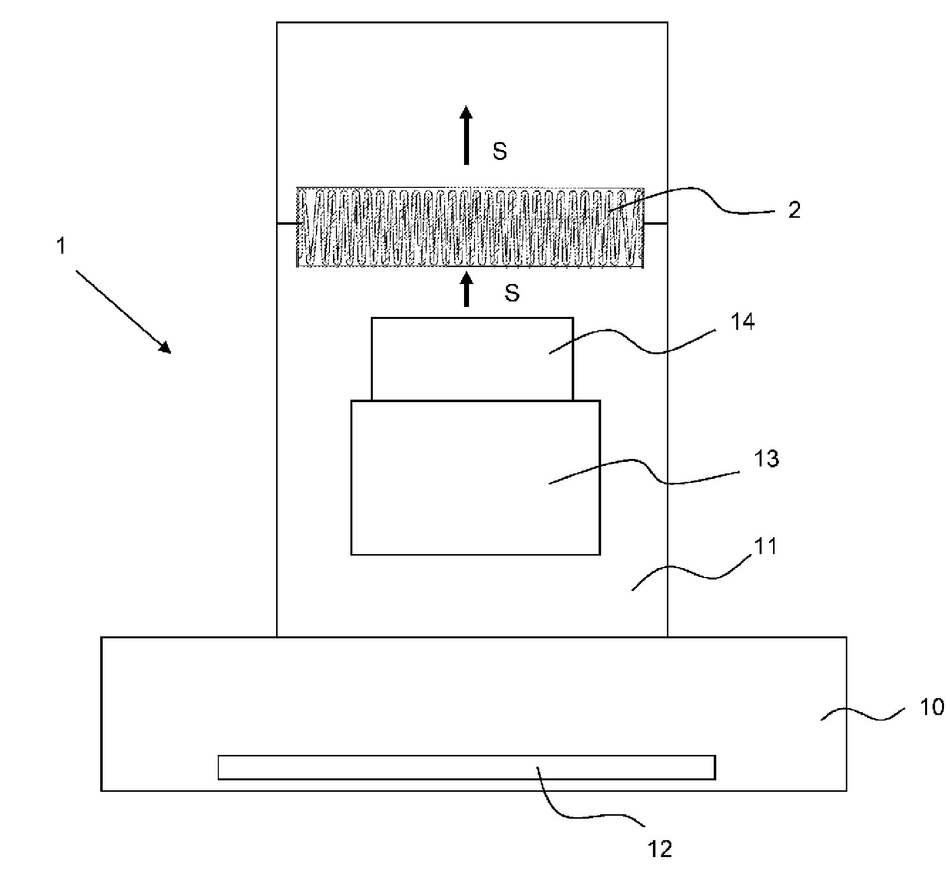
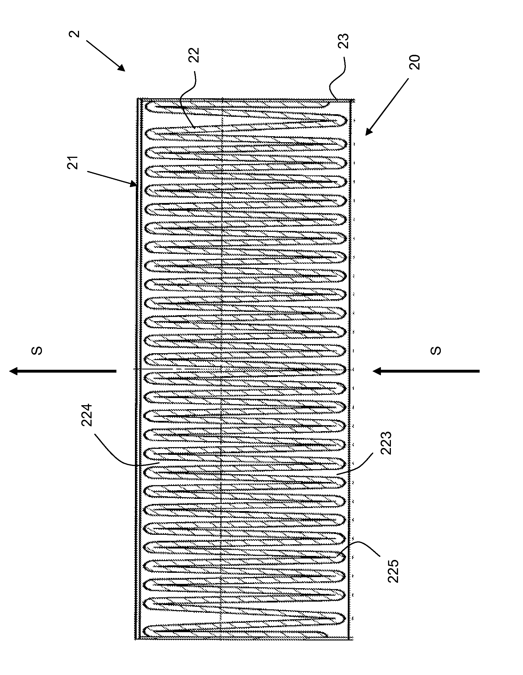
[0035] exist figure 1 A schematic perspective view of an embodiment of a filter element 2 according to the invention is shown in . The filter element 2 consists of a frame 23 and a filter 22 accommodated in the frame 23 . In the illustration shown, the frame 23 is open downwards and upwards, that is to say it consists only of the sides 231 to 234 . The odor filter 22 is accommodated in the frame 23 such that it does not extend beyond the height of the frame 23 . In the embodiment shown, the lower side of the frame 23 defines the flow-facing side 20 of the filter element 2 and the upper side defines the outlet side 21 . The main flow direction of the air is indicated by arrow S in the figure.

[0036] In the embodiment shown, frame 23 defines a rectangular interior. An odor filter 22 is arranged in the interior of the frame 23 .

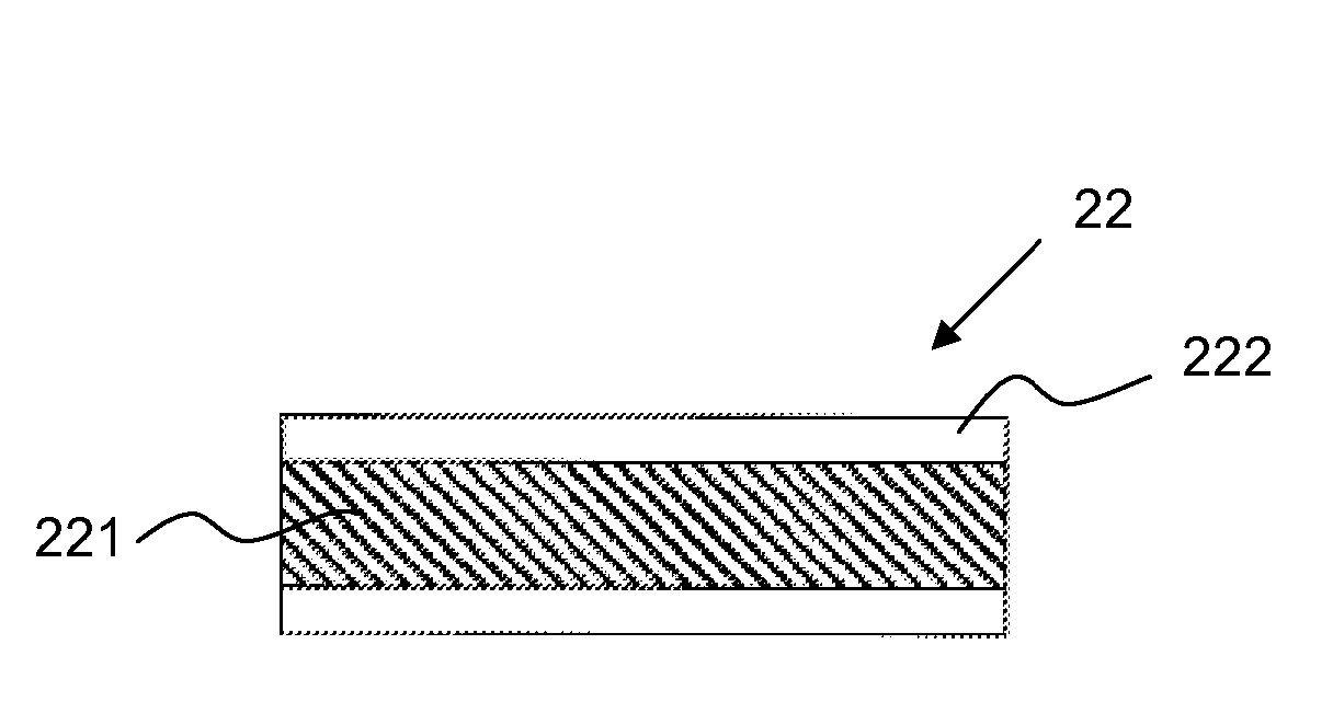
[0037] The odor filter 22 has a planar basic shape. exist image 3 A possible configuration of an odor filter is shown in . The odor filter 2...


PUM


Abstract

The invention relates to a filter element for an extractor hood (1) comprising an odor filter (22) and characterized in that the inflow side (20) of the filter element (2) is provided with recesses (223, 224) which are formed by the odor filter (22) and extend at least over half of the height of the filter element (2).

Description

technical field [0001] The invention relates to a filter element for a fume extraction hood and to a fume extraction hood. Background technique [0002] Known filter elements in fume extraction hoods for filtering or separating odorous substances usually have a non-woven fabric covering a filter material sheet, which consists of a foam material and is loaded with activated carbon. In this case, the activated carbon mat can be inserted into a plastic frame, on which the nonwoven material is welded on the upper and lower sides. [0003] A disadvantage of this known odor filter of the fume extraction hood is the small size of the active filter surface via which the air to be cleaned can enter the filter material mat. However, in order to achieve a sufficient cleaning of the air from odorous substances, it is therefore necessary to provide a plurality of filter elements. However, due to the installation space provided in the fume extraction hood, this cannot be realized or can...

Claims


Application Information

Patent Timeline
Patent Type & Authority Applications(China)
IPC IPC(8): B01D53/44B01D46/52B01D46/00
CPCB01D46/0038B01D46/10B01D46/521B01D53/44B01D2239/045B01D2253/102B01D2257/90F24C15/2035
Inventor H.艾希A.戈措尔J.克莱姆R.克诺赫U.诺伊曼A.普雷泽U.雷夫M.里希特M.施纳茨P.塞弗里德
Owner BOSCH SIEMENS HAUSGERATE GMBH
Learn More