
Vehicle control system and vehicle control method

A vehicle control system and vehicle control device technology, applied in the direction of electrical control, control devices, vehicle components, etc., can solve problems such as difficult design of acceleration operation, increase of vehicle speed, and driver's discomfort, so as to ensure continuity and ensure Maximum output, ensuring a smooth start or re-acceleration effect

Inactive Publication Date: 2012-09-12
TOYOTA JIDOSHA KK
View PDF9 Cites 10 Cited by
  • Summary
  • Abstract
  • Description
  • Claims
  • Application Information

AI Technical Summary

Problems solved by technology

In the known torque demand control as described above, the acceleration decreases at a higher rate as the vehicle speed increases, or it takes a long time to reach a steady state with the same acceleration operation amount, which causes the vehicle speed increase, which may make the driver feel uncomfortable
[0004] Moreover, it is difficult to design the optimal target acceleration related to the driver's accelerator operation amount by means of torque demand control using Weber-Fechner's law, and this control is not enough to achieve an acceleration that meets or adapts to the driver's feeling, so there is room for improvement

Method used


Image

  • Vehicle control system and vehicle control method
  • Vehicle control system and vehicle control method
  • Vehicle control system and vehicle control method

Examples


Embodiment Construction

[0031] An embodiment of the present invention will be described with reference to the drawings. It is to be understood that the present invention is not limited to the following examples. It can also be understood that constituent elements of the following embodiments include elements easily conceivable by those skilled in the art or elements substantially equivalent to the constituent elements of this embodiment. Moreover, the acceleration mentioned in the following embodiments includes not only the acceleration measured in the vehicle acceleration direction, but also the acceleration measured in the vehicle deceleration direction.

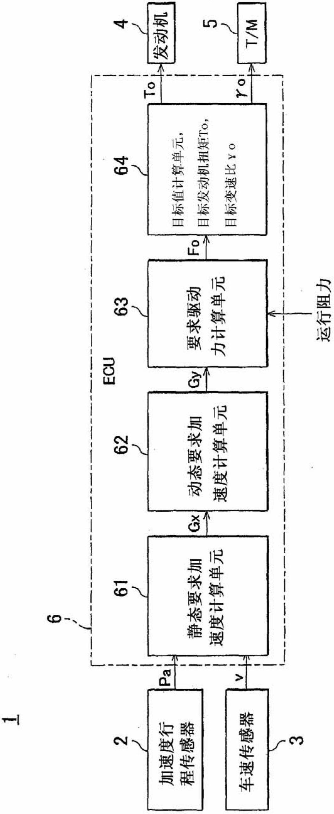
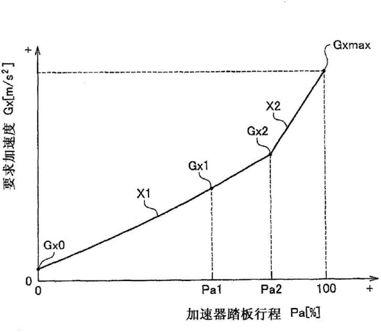
[0032] figure 1 The configuration or arrangement of a vehicle control system according to an embodiment of the present invention is schematically shown. figure 2 Indicates the relationship between required acceleration and accelerator pedal travel when the vehicle speed is constant.

[0033] Such as figure 1As shown in , at least a vehicle c...


PUM


Abstract

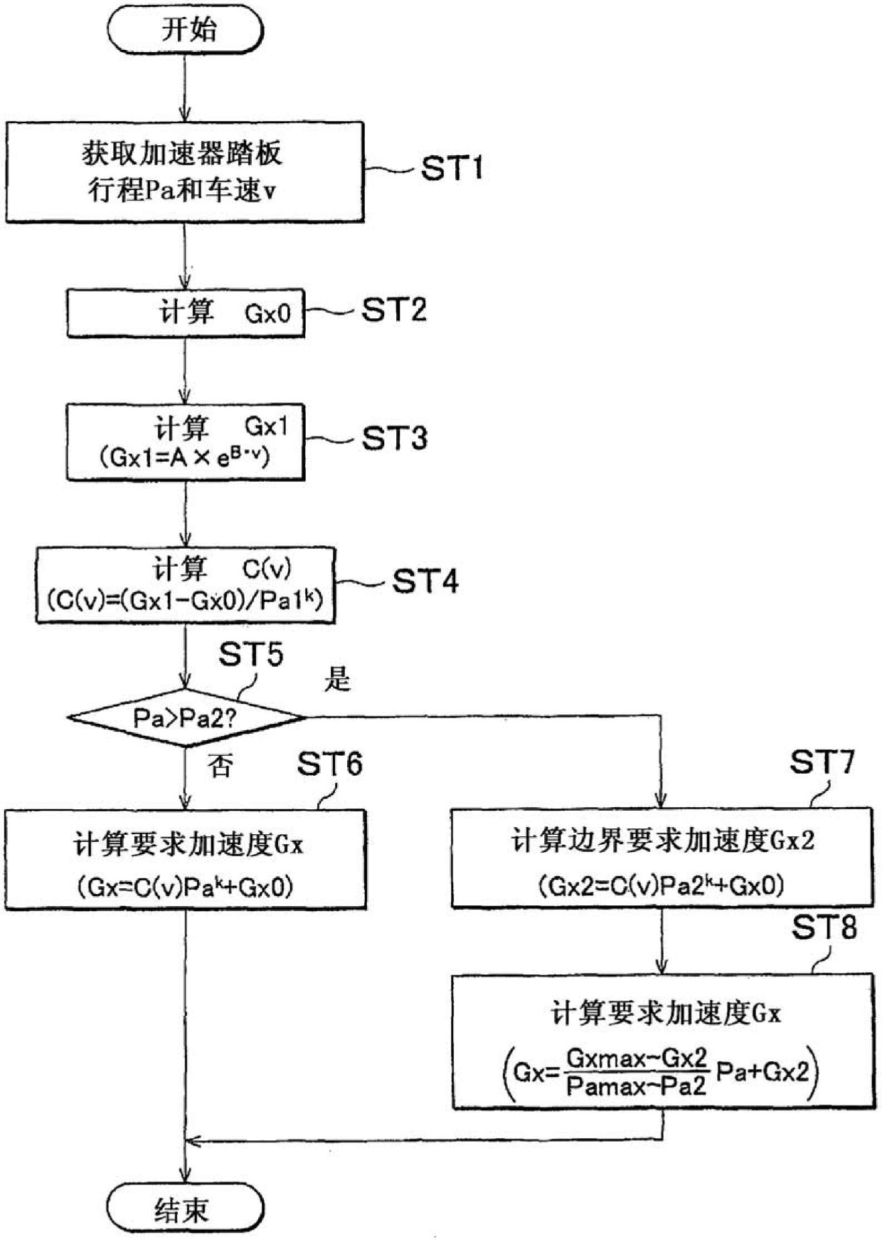
A vehicle control system includes an acceleration generating device (engine, T / M) that generates an acceleration applied to a vehicle, and a vehicle control device that controls the acceleration generating device, based on an accelerator pedal stroke Pa representing an operation of an accelerator pedal by a driver, and a vehicle speed v of the vehicle. In the vehicle control system or method, the vehicle control device controls the acceleration generating device, based on a required acceleration Gx that is determined based on a relationship between the accelerator pedal stroke Pa and the required acceleration, including, as a condition, an acceleration corresponding to a given accelerator pedal stroke, which is specified by a relationship between the vehicle speed and the acceleration when the accelerator pedal stroke is held at the given value.

Description

technical field [0001] The present invention relates to a vehicle control system and a vehicle control method. Background technique [0002] In recent years, a vehicle control called "torque demand control" is performed, under which a target acceleration as an acceleration required by the driver is determined based on the vehicle speed of the vehicle, and the driver's operation of the accelerator pedal is controlled based on the thus determined target acceleration Acceleration operation amount (accelerator pedal stroke, pedal effect, etc.) and engine throttle opening, fuel injection amount, ignition timing, etc., such as Japanese Patent Application Publication No. 63-025342 (JP-A-63-025342) mentioned. Although the target acceleration is determined based on the vehicle speed and the accelerator operation amount under the known torque demand control, the target acceleration determined based on the sensing of a professional discriminator cannot well achieve high-quality accele...

Claims


Application Information

Patent Timeline
Patent Type & Authority Applications(China)
IPC IPC(8): F02D41/04F02D41/08F02D41/10B60W10/06F02D11/10B60W10/04B60W10/10B60W30/00B60W30/18B60W30/188F02D29/02
CPCB60W10/06B60W30/1882B60W50/10F02D11/105F02D41/045F02D41/08F02D2200/501F02D2250/18F02D41/10B60W2540/103B60W2520/10F02D41/04
Inventor 能村真
Owner TOYOTA JIDOSHA KK
Learn More