Waste liquid container and liquid consumption apparatus

A storage body and waste liquid technology, applied in printing and other directions, can solve the problems of waste liquid tank hanging, waste liquid tank application, pin bending, etc.

Active Publication Date: 2012-09-19
SEIKO EPSON CORP
View PDF15 Cites 2 Cited by
  • Summary
  • Abstract
  • Description
  • Claims
  • Application Information

AI Technical Summary

Problems solved by technology

[0006] However, in the printer of Patent Document 1, since the pin is provided inside the attachment portion of the waste liquid container, the waste liquid tank inserted from the attachment port is not positioned inside where the pin engages with the elongated hole.
Therefore, during the period from when the waste liquid tank is inserted into the mounting port to reaching the inside where the long hole and the pin engage, the waste liquid tank may be caught in the mounting port. load problem
In addition, if the waste liquid tank is misaligned in the vertical direction, for example, during the period from the installation port to the inside, the pin will not be inserted correctly into the long hole of the waste liquid tank, resulting in poor installation.
Alternatively, there is a problem that if the pin is loosely inserted into the elongated hole, waste liquid will leak from the pin, and conversely, if the pin is inserted firmly into the elongated hole, the pin will be bent.

Method used


Image

  • Waste liquid container and liquid consumption apparatus
  • Waste liquid container and liquid consumption apparatus
  • Waste liquid container and liquid consumption apparatus

Examples


Embodiment Construction

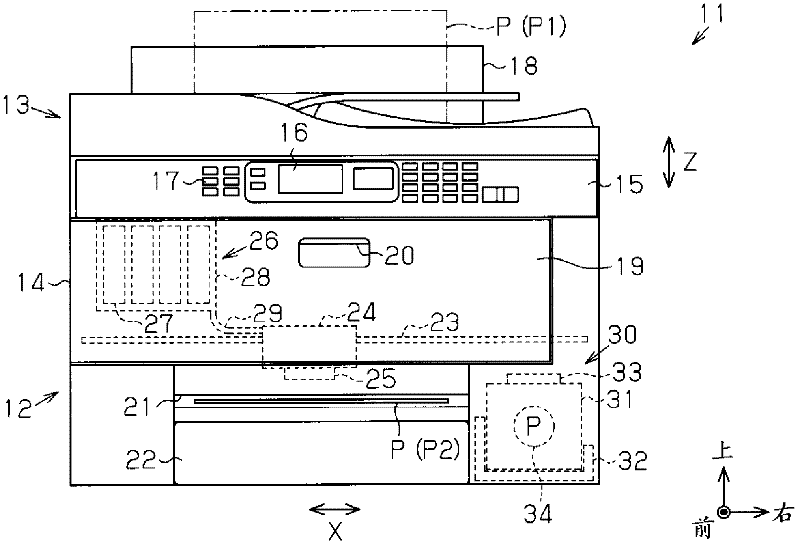
[0111] Hereinafter, an embodiment in which the present invention is embodied in a multifunction peripheral having the function of an inkjet printer will be described with reference to the drawings. In the following description, the "front-rear direction", "left-right direction", and "up-down direction" refer to the front-rear direction, left-right direction, and up-down direction indicated by arrows in the respective drawings. In addition, among the arrows showing upward, rightward, and forward in the drawings, a mark with a dot in the circle symbol (the figure of the front end of the arrow viewed from the front) means an arrow from the back of the paper toward the front, and the circle symbol The mark (the figure of the wing part of an arrow seen from the back) in which a cross is described in a symbol means the arrow which goes from the surface of the paper toward the quilt surface. In addition, the up-down direction is a vertical direction.

[0112] Such as figure 1 As sh...


PUM


Abstract

The present invention provides a waste liquid container and a liquid consumption apparatus. The waste liquid container (31) can be detachable relative to a recording part having liquid nozzles used for discharging waste liquid, and can store the waste liquid discharged from the liquid nozzles in the state of arranging on the recording part. The waste liquid container (31) comprises an engagement portion (68), the engagement portion (68) protrudes from a sidewall of the waste liquid container, and is closer to a downside of a vertical direction than a guide portion (52) of the recording part in the state of arranging on the recording part.

Description

[0001] The present invention refers to and quotes patent application numbers 2011-61176, 2011-61177, 2011-61178, 2011-61179, 2011-61180, 2011-61181, 2011-61182, and 2011 March 18, 2011 in Japan. The entire disclosure of the patent application No. 2011-50373 filed in Japan on March 8. technical field [0002] The present invention relates to a waste liquid storage body for storing waste liquid such as waste ink, and a liquid consumption device and a liquid ejection device provided with the waste liquid storage body. Background technique [0003] An inkjet printer is known as a liquid consuming device that consumes liquid by ejecting liquid onto an object such as paper. Conventionally, such a printer has a structure provided with a waste liquid storage body mounting portion for a waste liquid tank (waste liquid storage body) for storing waste ink (waste liquid) discharged from a liquid jet head that ejects ink. ) installation (for example, Patent Document 1). [0004] The wa...

Claims


Application Information

Patent Timeline
IPC IPC(8): B41J2/185
Inventor 原田秀平中田将范山本泰祐
Owner SEIKO EPSON CORP
Why Eureka
Try Eureka