
Improved structure of printing head of thermal printer

A technology of thermal printers and print heads, which is applied in printing and other directions, and can solve problems such as complex assembly, short service life, and easy fall-off of print heads

Active Publication Date: 2012-09-19
厦门爱印科技有限公司
View PDF6 Cites 4 Cited by
  • Summary
  • Abstract
  • Description
  • Claims
  • Application Information

AI Technical Summary

Problems solved by technology

Because this structure needs to fix the spring with screws, it is more complicated to assemble, and the screws that play a limiting role are easy to fall off due to the vibration of the print head during long-term use, and the service life is short

Method used


Image

  • Improved structure of printing head of thermal printer
  • Improved structure of printing head of thermal printer
  • Improved structure of printing head of thermal printer

Examples


Embodiment Construction

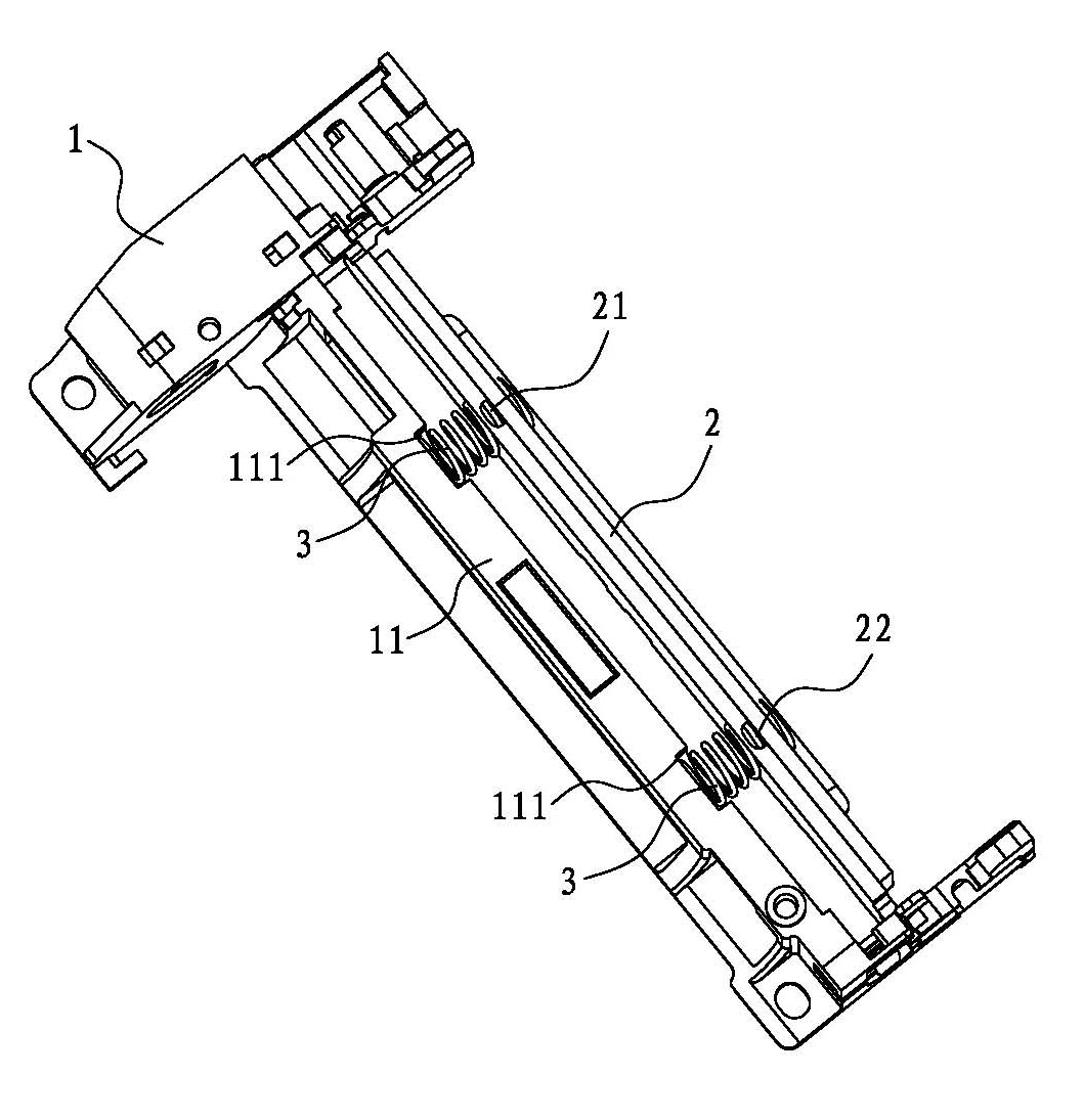
[0015] Such as figure 1 As shown, the present invention is an improved structure of a print head of a thermal printer, which includes a body 1, a mounting plate 2 and a spring 3.

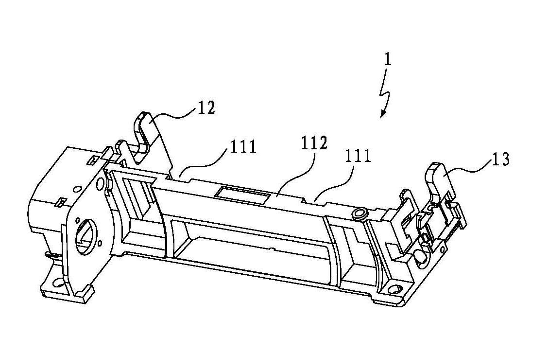
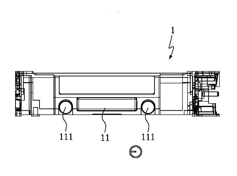
[0016] combine figure 2 , image 3 As shown, the body 1 has a spring mounting seat 11 and two cantilevers 12, 13, and the two cantilever arms 12, 13 extend vertically from both ends of the spring mounting seat 11 outwards. The two ends of the mounting plate 2 are interposed in the slots of the two cantilevers 12 and 13 of the body 1 . Two open slots 111 are provided on the spring mounting base 11, and the openings of the two opening slots 111 are located on the side wall 112 of the spring mounting base 11, so that the spring 3 can slide in through the openings during assembly.

[0017] The mounting plate 2 is provided with two protrusions 21, 22 for nesting the spring 3; one end of the spring is sleeved on the two protrusions 21, 22 and leans against the mounting plate 2, The other end of the s...


PUM


Abstract

The invention discloses an improved structure of a printing head of a thermal printer. The improved structure comprises a body, a mounting plate and a spring, wherein the two ends of the mounting plate are inserted into the body at an interval; and the two ends of the spring are propped between a spring mounting seat of the body and the mounting plate; more than one open slot is arranged on the spring mounting seat; and a limiting rod with a limiting function is arranged at the center of the spring. When the improved structure is assembled, one end of the spring is in sleeve joint with a convex column of the mounting plate, and the other end of the spring slides into the open slot from the opening of the open slot of the spring mounting seat and is propped in the open slot of the spring mounting seat, thus the conventional process of mounting the printing head with a bolt is eliminated, and the assembly is very convenient and quick. Moreover, through the fixing mode with the spring, the problem that the bolt drops due to the vibration of the printing head after long-term use is avoided, and thus the mounting is firmer and more reliable.

Description

technical field [0001] The invention relates to a thermal printer, in particular to an improved structure of a print head of a thermal printer. Background technique [0002] The working principle of a thermal printer is that a semiconductor heating element is installed on the print head. After the print head is heated and contacts the thermal printing paper, the required pattern can be printed out. Its principle is similar to that of a thermal fax machine. The print head of a thermal printer is a key component of a thermal printer. A conventional print head is mainly composed of a body, a mounting plate and a spring, and the spring is fixed on the mounting plate by screws. Since the spring needs to be fixed by screws in this structure, the assembly is relatively complicated, and the screws that act as a limiter are easy to fall off due to the vibration of the print head during long-term use, and the service life is short. Contents of the invention [0003] The object of ...

Claims


Application Information

Patent Timeline
IPC IPC(8): B41J2/335
Inventor 戴华军陈植
Owner 厦门爱印科技有限公司
Learn More