Rubber rod clamp

A glue rod and beading technology, which is applied in printing, binding, etc., can solve the problems of piercing documents, high production costs, scratching human hands, etc., and achieve the effects of meeting environmental protection requirements, easy replacement, and eliminating edges and corners

Inactive Publication Date: 2012-09-19
东莞市新原文具有限公司
View PDF8 Cites 0 Cited by
  • Summary
  • Abstract
  • Description
  • Claims
  • Application Information

AI Technical Summary

Problems solved by technology

This kind of handle clip is made of metal, and its components cannot be assembled and disassembled by hand. For example, the ends of the first end and the second end of the rotating arm need to be processed by equipment, and the first end of the rotating arm and the second end The ends of the ends are flattened, so that protrusions are formed at the ends of the first and second ends of the rotating arm, so that the rotating arm can be limited on the handle clamp to prevent the rotating arm from coming out; therefore, the assembly of the handle clamp requires the support of the equipment, and the assembly work Lower efficiency and higher production costs
The metal handle has many edges and corners, which makes the hand feel very bad. In addition, the protrusions at the end of the first end and the second end of the rotating arm protrude from the outer surface of the outer end of the bead, and the protrusions are sharp. The first end of the rotating arm and the The protruding portion at the end of the second end can scratch the hand and puncture the document, causing considerable distress to the user

Method used


Image

  • Rubber rod clamp
  • Rubber rod clamp
  • Rubber rod clamp

Examples


Embodiment 1

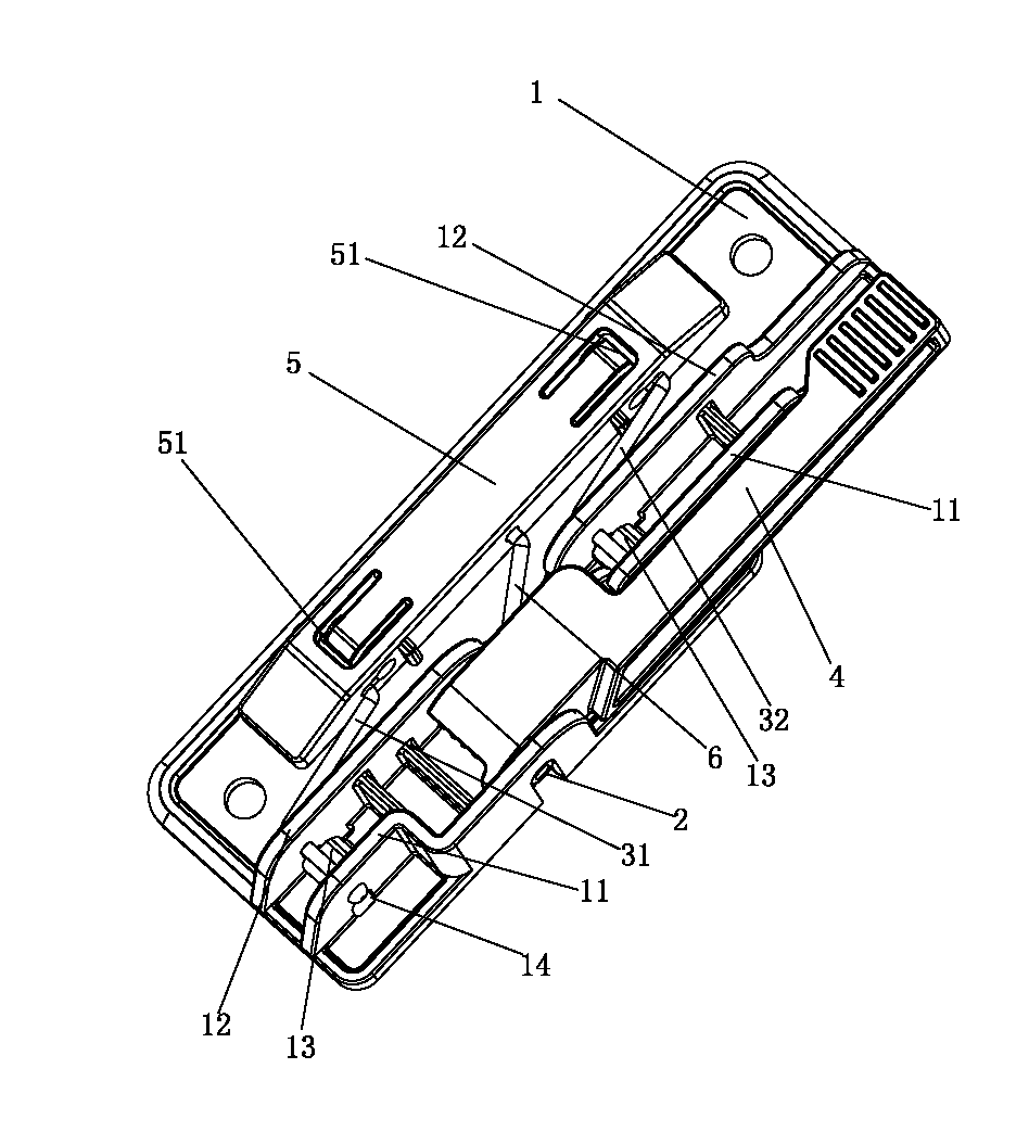
[0041] like Figure 1 to Figure 3As shown, a glue rod clamp includes a front arm 31, a rear arm 32 and a pin 2, and a base plate 1 made of plastic, a handle 4 and a bead 5, and the handle 4 is pivotally connected to the side of the base plate 1 through the pin 2. On the side 11, the pin 2 is covered with a torsion spring 6, and the first end and the second end of the torsion spring 6 are respectively connected to the bead 5 and the handle 4; Arm 31 and rear pivot arm 32 are respectively arranged on the both sides of torsion spring 6, and the first end and the second end of front pivot arm 31 are respectively movably connected to press bar 5 and base plate 1; To the outer surface of the press bar 5, and the first end of the front swing arm 31 is detachably connected with the press bar 5, the end of the second end of the front swing arm 31 stretches out to the outer surface of the side 11, and the second end of the front swing arm 31 The end is detachably connected with the sid...

Embodiment 2

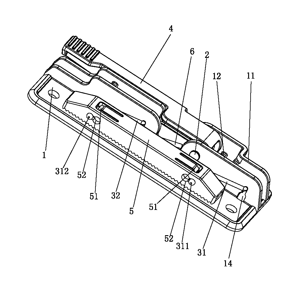
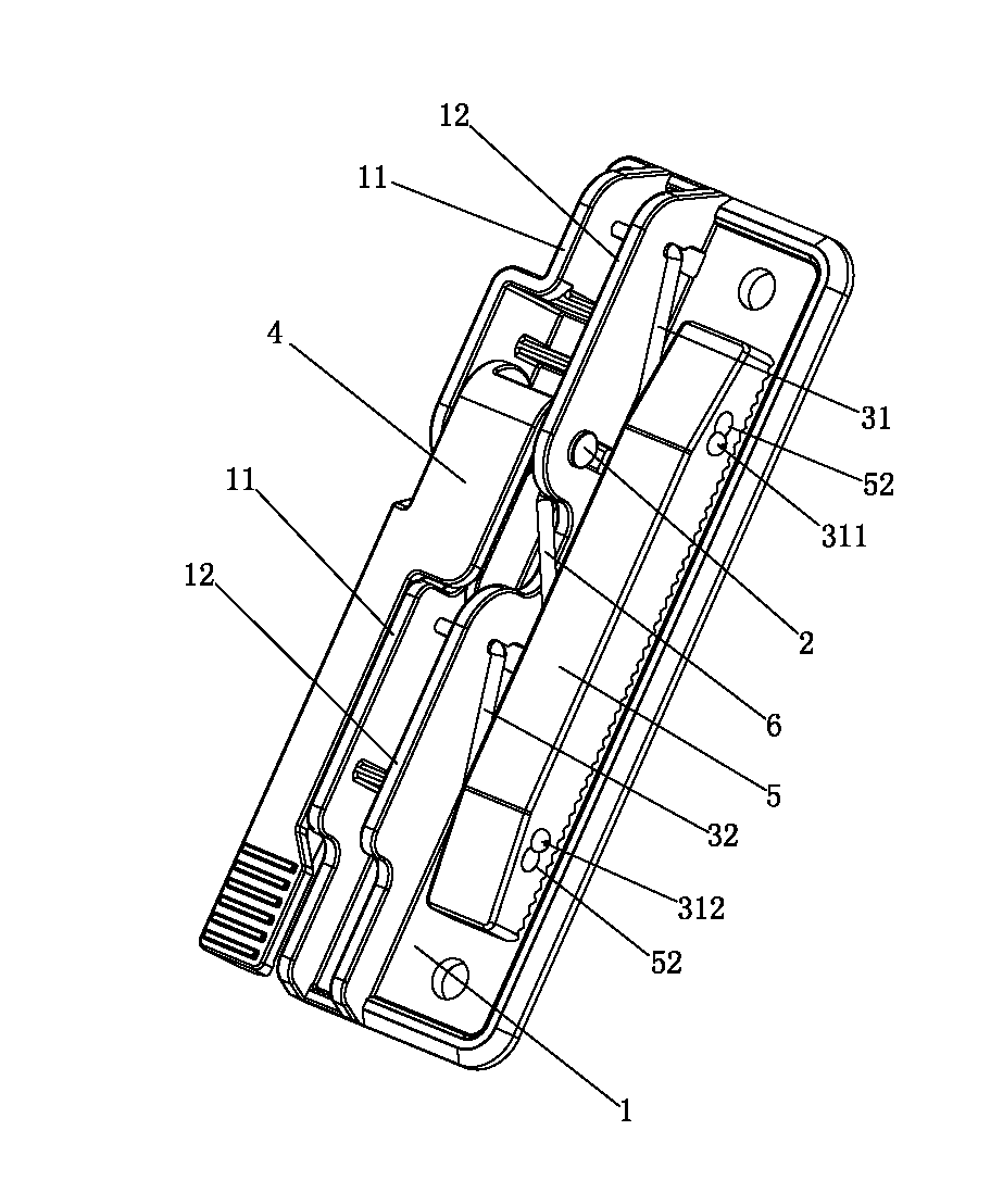
[0054] like Figure 4 to Figure 8 As shown, the difference between this embodiment and the first embodiment is:

[0055] Wherein, the side of the inner end of the bead 5 and the side of the outer end are respectively provided with a first T-shaped groove 52 for installing the first end of the front arm 31, and the first T-shaped groove 52 on the inner end of the bead 5 and the outer end of the bead 5 A shaft hole 7 is formed alternately at one end with a smaller width; the first end of the front pivot arm 31 is passed through the shaft hole 7 formed alternately by the first T-shaped groove 52 at the inner end and outer end of the bead 5 , and the front pivot arm 31 The first end of the first end is formed with a first abutment 311 of the front pivot arm, and the first abutment 311 of the front pivot arm abuts against the side of the outer end of the bead 5 . When assembling, the first abutment 311 of the front rotating arm at the first end of the front rotating arm 31 first p...

Embodiment 3

[0058] like Figure 9 As shown, the difference between this embodiment and embodiment one or embodiment two is:

[0059]Wherein, the side of the inner end of the press bar 5 is provided with a perforation 53 for the first end of the front swing arm 31 to pass through, and the side of the outer end of the press bar 5 is provided with a gap 54 for the first end of the front swing arm 31 to pass through, and This gap 54 penetrates the side surface of the outer end of the bead 5 and the top surface of the bead 5, and the first end of the front arm 31 passes through the perforation 53 of the inner end of the bead 5 and the breach 54 of the outer end of the bead 5, and the first end of the front arm 31 The end is formed with a first bending hook 312 of the front turning arm, and the first bending hook 312 of the front turning arm abuts against the side of the outer end of the bead 5 . During assembly, the first end of the front swing arm 31 passes through the perforation 53 at the ...


PUM


Abstract

The invention belongs to the technical field of office supplies, and in particular relates to a rubber rod clamp. The rubber rod clamp comprises a front rotating arm, a rear rotating arm, a pin, and a bottom plate, a handle and a press strip which are made of plastics, wherein the handle is pivoted on the side edge of the bottom plate through the pin; a first end and a second end of the front rotating arm and a first end and a second end of the rear rotating arm are connected with the press strip and the bottom plate respectively; the tail ends of the first ends of the front rotating arm and the rear rotating arm are extended out of the outer side surface of the press strip, and the front rotating arm and the rear rotating arm are connected with the press strip in a detachable mode; and the tail ends of the second ends of the front rotating arm and the rear rotating arm are extended out of the outer side surface of the side edge, and the front rotating arm and the rear rotating arm are connected with the side edge in a detachable mode. The rubber rod clamp is mainly made of plastic materials and can be manufactured in an integrated mode, so that the cost is saved; edges and corners of metal pieces are eliminated by the plastic rubber rod clamp, and the plastic rubber rod clamp has smooth handfeel compared with a metal handle clamp; and in addition, the rubber rod clamp is convenient to assemble and disassemble, and a single part is convenient to replace, so that metal and rubber materials can be conveniently separated and recycled when products are discarded, and the rubber rod clamp extremely meets the requirement of environment friendliness.

Description

technical field [0001] The invention belongs to the technical field of office supplies, and in particular relates to a glue bar clip. Background technique [0002] File folder is a tool used to store, protect and standardize the management of paper documents. It is an indispensable office product for enterprises, government departments and schools to organize and store documents. It can hold various paper documents. [0003] Folders generally include a folder body and a handle clamp fixed on the folder body. Existing handle clamps generally include a base plate, pins, rotating arms, handles and beading bars. The handle is pivotally connected to the side of the base plate through pins. The first end and the second end of the arm are respectively connected to the bead and the bottom plate, the end of the first end of the rotating arm protrudes to the outside of the bead, and the end of the second end of the rotating arm protrudes to the outer surface of the side. This kind o...

Claims


Application Information

Patent Timeline
Patent Type & Authority Applications(China)
IPC IPC(8): B42F1/02
Inventor 林春海
Owner 东莞市新原文具有限公司
Why Eureka
Try Eureka