Laser diffraction type multi-system axis parallelism detecting device

A parallelism detection and laser diffraction technology, which is used in weapon testing, weapon accessories, offensive equipment, etc., can solve the problems of time-consuming and laborious, and keep still, and achieve the effect of clear imaging.

Inactive Publication Date: 2012-09-19
王刚
4 Cites 8 Cited by

AI-Extracted Technical Summary

Problems solved by technology

However, the disadvantage of this method is that the platform of the device under test and the target board must be kept stationary, so as to stabil...

Method used

When using the present embodiment to carry out axial parallelism detection to artillery system, at first laser diffraction light emitter is inserted in the gun barrel, and the optical axis of laser diffraction light emitter has just represented gun barrel axis, then looks for distance ( 100m-1Km) suitable reflective screen, the reflective screen can be non-cooperative objects such as buildings, ships, billboards, etc. After finding a suitable reflective screen, record the azimuth and pitch angle data of the artillery, and put the radar/photoelectric observation device Adjust to this position, then emit laser diffracted light, adjust the zoom lens group to make the diffraction stripes on the reflective screen clear and diffusely reflected by the reflective screen, at this time, the diffraction halo ...

Abstract

The invention discloses a laser diffraction type multi-system axis parallelism detecting device. The laser diffraction type multi-system axis parallelism detecting device is mainly characterized in that laser beams capable of being detected by a television detector, such as red laser and green laser, are transmitted, after passing through collimating lens, the laser beams enter a diffraction grating device to be diffracted to obtain diffraction laser beams, wherein the direction of zero-level diffraction laser is identical to that of the axis of a gun barrel, the diffraction laser beams are projected to a distant non-cooperative reflecting screen via a lens system to form a diffraction image. The diffraction image enters a view field of a radar/photoelectric television observation device via diffuse reflection to image, an angle between the diffraction image and an electric cross reference is calculated from the image, and errors of axis parallelism between a gum and radar/photoelectricity are determined from data processing. The laser diffraction type multi-system axis parallelism detecting device has the advantages that the device is not limited by distances of baselines among platforms during usage, and can be used for detecting the axis parallelism of a plurality of devices simultaneously.

Application Domain

Weapon testing

Technology Topic

Data processingGreen laser +9

Image

  • Laser diffraction type multi-system axis parallelism detecting device
  • Laser diffraction type multi-system axis parallelism detecting device
  • Laser diffraction type multi-system axis parallelism detecting device

Examples

  • Experimental program(1)

Example Embodiment

[0010] The present invention will be further described in detail below in conjunction with the accompanying drawings and preferred embodiments.
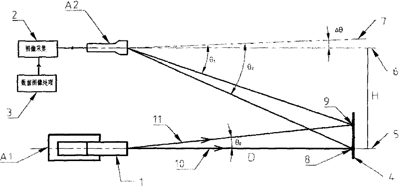
[0011] figure 1 It is a schematic diagram of the principle of the present invention, and the launch angle from the device 1 is θ 0 The two laser beams 10 and 11, the direction of the laser beam 10 represents the axis 5 of the platform A1, and the two laser beams are projected on the reflective screen 4 at a distance D to form bright spots 8 and 9, which are diffusely reflected by the reflective screen. The television observation device on platform A2 detects the imaging. The baseline distance between platform A1 and platform A2 is H. The position of the TV electric cross represents the axis position of the TV detector and is also the reference center during measurement. When the platform A1 is parallel to the platform A2, the axis, that is, the electric cross is 6. When it is not parallel, the position of the electric cross is assumed to be 7. At this time, the parallel axis 6 and the non-parallel axis, the electric cross 7, have Δθ, that is, the platform A1 Axis parallelism error with A2. Taking the electric cross 7 as the reference center, the measurement angle of the bright spots 9 and 8 can be obtained as θ 1 , θ 2 , according to the geometric relationship, Δθ can be calculated.
[0012]
[0013] in: The quadrant of the angle is determined by the coincidence of a and b.
[0014] a = BC + AD 2 , b = BD - AC 2 - AD - BC E , c = - AC + BD 2
[0015] A=sin(θ 2 ), B=cos(θ 2 ), C=sin(θ 1 ), D=cos(θ 1 ), E=tan(θ 0 )
[0016] figure 2 It is a schematic diagram of a preferred embodiment of the present invention. The laser diffraction light transmitter includes a laser source 12 , a beam expanding collimator lens 13 , a diffraction grating device 14 , and a variable focus lens group 15 . The laser source 12 emits a laser beam, which becomes parallel light after passing through the beam expanding collimating lens 13. The parallel light enters the diffraction grating device 14 and is diffracted. The diffraction angle corresponding to the first-order diffraction is θ. 0 , the diffracted light is projected to the non-cooperative screen 4 through the variable-focus lens group 15 to form diffraction fringes, and the focal length of the variable-focus lens group 15 is adjusted to make the diffraction fringes on the reflection screen 4 clear. According to geometric optics, the parallel light incident obliquely at a certain angle is condensed and imaged by the lens, no matter how the focal length of the lens changes, the direction of the chief ray will not change, which is also the precondition for the establishment of the present invention. The laser light source 12 can be a light source that can be detected by a television, such as red light and green light, the diffraction grating device 14 is a ring diffraction grating device, and the focal length range of the variable focus lens group 15 is 100m-1Km.
[0017] The operation and use process of the present invention will be described below in conjunction with the preferred embodiment.
[0018] When using this embodiment to detect the axis parallelism of the artillery system, first insert the laser diffraction light transmitter into the gun barrel, the optical axis of the laser diffraction light transmitter represents the axis of the gun barrel, and then find the distance (100m-1Km ) Appropriate reflective screen, the reflective screen can be non-cooperative objects such as buildings, ships, billboards, etc. When a suitable reflective screen is found, record the azimuth and pitch angle data of the artillery, and adjust the radar/photoelectric observation device to this position, then emit laser diffracted light, adjust the zoom lens group to make the diffraction fringes on the reflective screen clear and diffusely reflected by the reflective screen. At this time, the diffraction halo appears in the field of view of the radar/photoelectric TV detector, record it. The measured angle θ of the zero-order and first-order of the diffraction ring image to the electric cross or cross reticle, respectively 1 , θ 2 , using these two angle values ​​and the first-order diffraction angle θ 0 The parallelism error between the artillery axis and the radar/optical axis can be calculated. In order to reduce the system error caused by the inconsistency between the optical axis of the laser diffraction light transmitter and the barrel axis, the laser diffraction light transmitter can be rotated 360° in the barrel during use, and the measurement data at different rotation angles can be recorded for statistical processing. , the system error can be eliminated and the measurement accuracy can be improved.
[0019] Although the present invention has been described by way of example apparatus, those skilled in the art will recognize that additions, deletions, changes and substitutions may be made without departing from the spirit, scope and claims of the invention.

PUM

no PUM

Description & Claims & Application Information

We can also present the details of the Description, Claims and Application information to help users get a comprehensive understanding of the technical details of the patent, such as background art, summary of invention, brief description of drawings, description of embodiments, and other original content. On the other hand, users can also determine the specific scope of protection of the technology through the list of claims; as well as understand the changes in the life cycle of the technology with the presentation of the patent timeline. Login to view more.

Similar technology patents

Focusing device and method for satellite remote sensing camera

InactiveCN105334594AAccurate small range focusingClear imagingProjector focusing arrangementCamera focusing arrangementCamera lensSatellite remote sensing
Owner:NAT UNIV OF DEFENSE TECH

Laser night vision auxiliary driving laser illuminator

ActiveCN103792666AAdapt to the needs of assisted drivingClear imagingMountingsPhotographyCamera lensLaser light
Owner:山东神戎电子股份有限公司

Vehicle chassis inspection system

Owner:漳州市玉山电子制造有限公司

Classification and recommendation of technical efficacy words

Why Eureka
Try Eureka