
Real-time detecting instrument for two-shaft rotating angle differences

A detector and two-axis rotation technology, which is applied in the field of detectors to detect the difference between two-axis rotation angles, can solve the problems that errors affect measurement accuracy and cannot truly and accurately respond to two-axis rotation speeds, and achieve improved measurement accuracy, low cost, and measurement high precision effect

Active Publication Date: 2014-07-30
LIUZHOU VOCATIONAL & TECHN COLLEGE
View PDF4 Cites 0 Cited by
  • Summary
  • Abstract
  • Description
  • Claims
  • Application Information

AI Technical Summary

Problems solved by technology

[0002] The speed of the two shafts needs to be the same, and the speed can be controlled by the mechanical synchronization mechanism. However, whether the two shaft speeds controlled by the mechanical synchronization mechanism are exactly the same or within the error range can only be determined by measurement, but there is currently no special use in the market. The measuring instrument that measures the speed difference between two shafts in real time can only measure the speed of one shaft through the speed measuring instrument, and then use the same speed measuring instrument to measure the speed of the other shaft, and compare the two shaft speeds through the two measured values. Or within the error range, this measurement method has certain limitations. The rotational speed of the two shafts is not measured at the same time. It is very easy to affect the measurement due to the power change of the drive device driving the two shafts at different times or external factors. The measured data often cannot be measured. True and accurate response to whether the rotational speeds of the two shafts are the same or within the error range
If two speed measuring instruments are used to measure the speed of two shafts at the same time, the measurement accuracy will also be affected by the error between different speed measuring instruments
In addition, after the above two measurement methods are measured, the difference must be obtained through manual calculation.

Method used


Image

  • Real-time detecting instrument for two-shaft rotating angle differences

Examples


Embodiment Construction

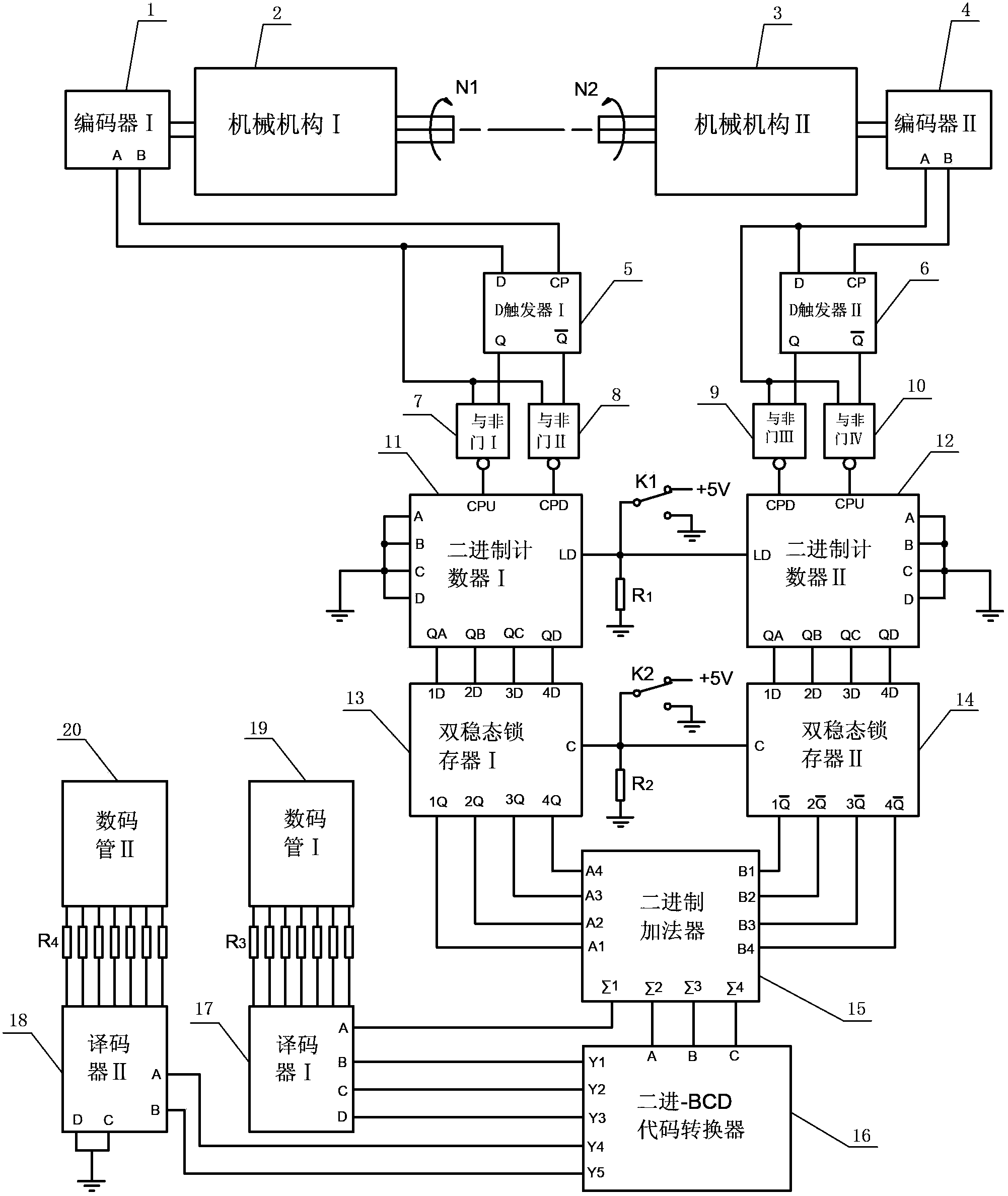
[0015] Such as figure 1 As shown, the real-time two-axis rotation angle difference detector of the present invention (hereinafter referred to as "the detector") includes an encoder, a D flip-flop, a NAND gate, a binary counter, a bistable latch, and a binary adder 15 , Binary-BCD code converter 16, decoder and digital tube.

[0016] The encoder includes an encoder I1 directly connected to the output shaft of the mechanical mechanism I2 and an encoder II4 directly connected to the output shaft of the mechanical mechanism II3. The D flip-flop includes a D flip-flop I5 connected to the output end of the encoder I1 and a D flip-flop II6 connected to the output end of the encoder II4, and the output end of the encoder I1 is connected to the input end and the control end of the D flip-flop I5 respectively. Connection, the output end of the encoder II4 is respectively connected with the input end and the control end of the D flip-flop II6.

[0017] The NAND gate includes a NAND gat...


PUM


Abstract

The invention relates to a detecting device, in particular to a real-time detecting instrument for two-shaft rotating angle differences. The real-time detecting instrument for the two-shaft rotating angle differences comprises encoders, D triggers, NAND gates, binary counters, bi-stable latches, a binary adder, a binary-BCD (binary-coded decimal) code converter, decoders and nixie tubes. The encoders include an encoder I directly connected with an output shaft of a mechanism I and an encoder II directly connected with an output shaft of a mechanism II, the encoder I and the encoder II respectively collect rotating angle signals of the output shaft of the mechanism I and of the output shaft of the mechanism II and convert the rotating angle signals into electric signals to pass through the D trigger I, the D trigger II, the NAND gate I, the NAND gate II, the NAND gate III, the NAND gate IV, the binary counter I, the binary counter II, the bi-stable latch I and the bi-stable latch II, differences of pulse numbers are obtained through computing of the binary adder, and the nixie tubes are used for displaying the differences of the pulse numbers by the aid of the binary-BCD code converter and the decoders. The two-shaft rotating angle differences at the same moment can be detected by the same instrument, defects of the prior art are overcome, and detecting accuracy is improved effectively.

Description

technical field [0001] The invention relates to a detection instrument, in particular to a detection instrument for detecting the rotation angle difference of two axes. Background technique [0002] The speed of the two shafts needs to be the same, and the speed can be controlled by the mechanical synchronization mechanism. However, whether the two shaft speeds controlled by the mechanical synchronization mechanism are exactly the same or within the error range can only be determined by measurement, but there is currently no special use in the market. The measuring instrument that measures the speed difference between two shafts in real time can only measure the speed of one shaft through the speed measuring instrument, and then use the same speed measuring instrument to measure the speed of the other shaft, and compare the two shaft speeds through the two measured values. Or within the error range, this measurement method has certain limitations. The rotational speed of the...

Claims


Application Information

Patent Timeline
Patent Type & Authority Patents(China)
IPC IPC(8): G01P3/481
Inventor 黄应勇钟俏灵曾林邓海英
Owner LIUZHOU VOCATIONAL & TECHN COLLEGE
Learn More