Linear light source, light guiding body and optical scanning module

A linear light source and light guide technology, applied in the field of light sources, can solve problems such as inconvenience and poor utilization of light energy.

Inactive Publication Date: 2012-09-19
LITE ON OPTO TECH (CHANGZHOU) CO LTD +2
View PDF3 Cites 5 Cited by
  • Summary
  • Abstract
  • Description
  • Claims
  • Application Information

AI Technical Summary

Problems solved by technology

[0005] It can be seen that the light energy utilization rate of the linear light source of the existing optical scanning module is not good, and a breakthrough is urgently needed to reduce energy consumption and improve scanning quality
[0006] It can be seen that the above-mentioned existing optical scanning module obviously still has inconvenience and defects in structure and use, and needs to be further improved urgently.

Method used


Image

  • Linear light source, light guiding body and optical scanning module
  • Linear light source, light guiding body and optical scanning module
  • Linear light source, light guiding body and optical scanning module

Examples


Embodiment Construction

[0030] In order to further explain the effect of the technical means adopted by the present invention to achieve the intended purpose of the invention, the specific implementation and structure of the linear light source, light guide body and optical scanning module proposed according to the present invention will be described below in conjunction with the accompanying drawings and preferred embodiments. , features and their effects are described in detail below.

[0031] Before the present invention is described in detail, it should be noted that in the following description, similar components are denoted by the same numerals.

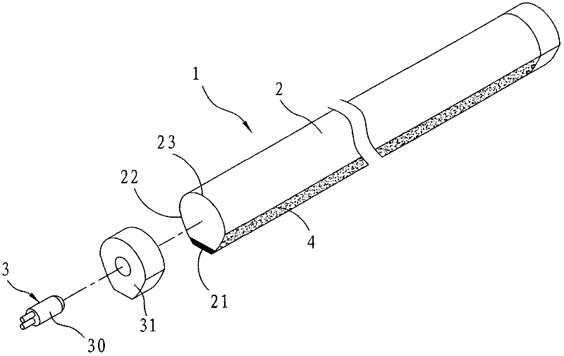
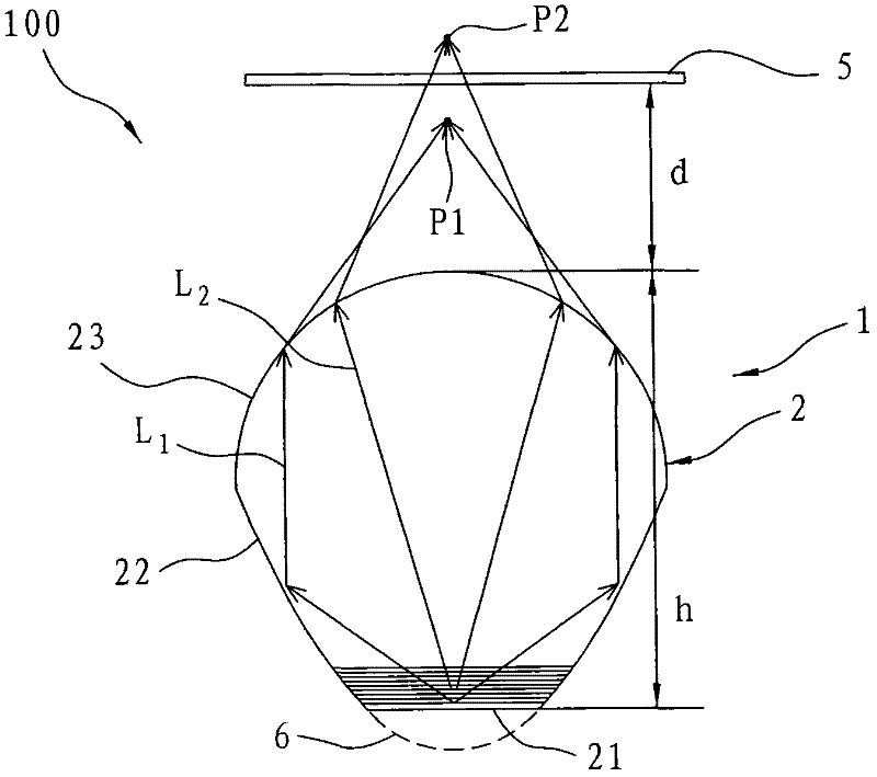
[0032] refer to figure 2 and image 3 , the linear light source 1 of the present invention is applied to an optical scanning module 100 , and the optical scanning module 100 also includes a scanning target 5 . The linear light source 1 is used to emit light and irradiate the scanning target 5 . Since the electronic components that the optical sca...


PUM


Abstract

The invention relates to a linear light source. Emitted light shines on an object. The linear light source comprises a light guiding body, a light-emitting diode (LED) unit and a reflecting layer. The emitted light is transmitted in the light guiding body. The light guiding body is provided with a bottom face, two reflecting faces extending from two sides of the bottom face respectively and a spotlight cambered surface connected with the two reflecting faces, wherein an opening of the spotlight cambered surface faces the bottom face. The two reflecting faces are arranged on two symmetrical sides of a hypothetical paraboloid, and an opening of the paraboloid faces the spotlight cambered surface. The reflecting layer is arranged on a reflecting face of the light guiding body. By means of the characteristics that light emitted from a focus of the paraboloid face becomes parallel light through reflection, the cambered surface is adopted for focusing the light, and the light is effectively converged on the object.

Description

technical field [0001] The invention relates to a light source, in particular to a linear light source applicable to an optical scanning module. Background technique [0002] The optical scanning module is used in scanners, fax machines, or multi-function printers (MPF, multi-function printers) that integrate photocopying, scanning, printing, and faxing. The optical scanning module usually includes a light source, reflective lens, focusing lens and an image sensor. [0003] The light source can emit light to irradiate the scanning target, and the scanning target has a pattern of the target; the image sensing component receives the reflected light to generate an electronic signal corresponding to the pattern of the target. The above-mentioned light source generally uses a cold cathode fluorescent lamp (CCFL) to emit white light, and irradiates the object to be scanned through a narrow and long hole. However, cold-cathode fluorescent lamps not only need an inverter to provid...

Claims


Application Information

Patent Timeline
Patent Type & Authority Applications(China)
IPC IPC(8): G02B6/00G02B26/10F21V13/00F21Y101/02
CPCH04N1/02835H04N1/02825G02B3/0056G02B6/001G02B6/0038H04N1/02895G02B6/0006G02B6/0055G02B6/0001
Inventor 林峻枫
Owner LITE ON OPTO TECH (CHANGZHOU) CO LTD
Why Eureka
Try Eureka