Ceiling decorative lamp strip structure

A technology for ceilings and light strips, applied in building components, lighting devices, lighting devices, etc., can solve the problems of destroying the integrity of patterns on the ceiling, affecting the aesthetics and cleanliness of the ceiling, and poor aesthetics and cleanliness of the ceiling. Achieve the effect of simple and stable overall structure, reduce glare and ensure aesthetics

Inactive Publication Date: 2021-01-05
深圳市尚石设计有限公司
View PDF7 Cites 1 Cited by
  • Summary
  • Abstract
  • Description
  • Claims
  • Application Information

AI Technical Summary

Problems solved by technology

At present, the light strips are generally installed directly on the ceiling. During the daytime, the light strips not only fail to illuminate, but also destroy the integrity of the patterns on the ceiling, making the ceiling less beautiful and tidy.
[0003] Regarding the related technologies mentioned above, the inventor believes that there is a defect that the light strip affects the aesthetics and cleanliness of the ceiling during the day

Method used


Image

  • Ceiling decorative lamp strip structure
  • Ceiling decorative lamp strip structure
  • Ceiling decorative lamp strip structure

Examples


Embodiment 1

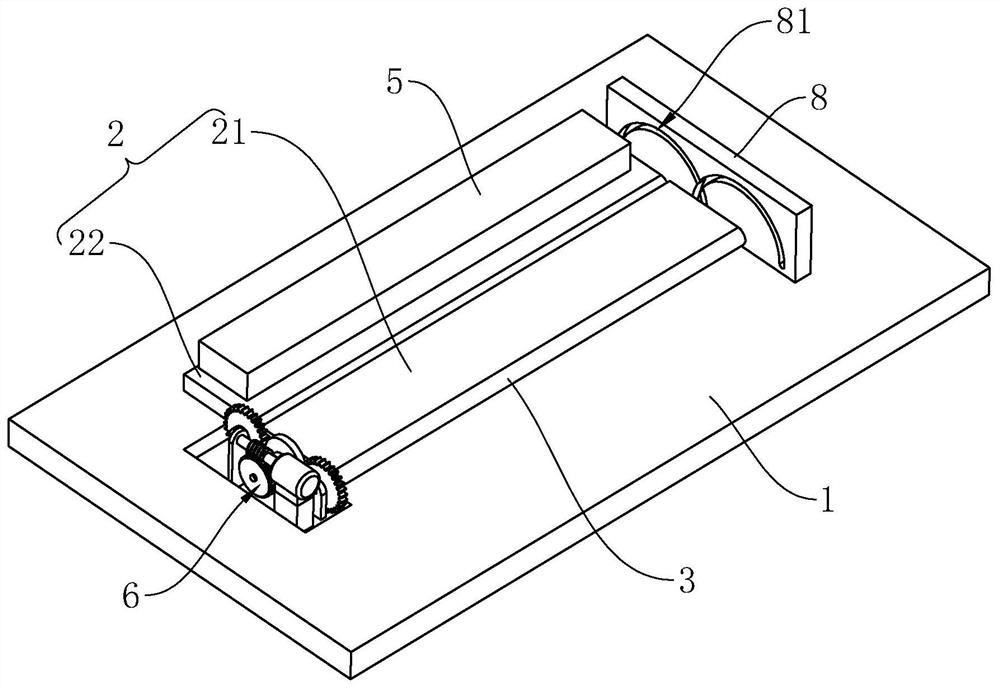
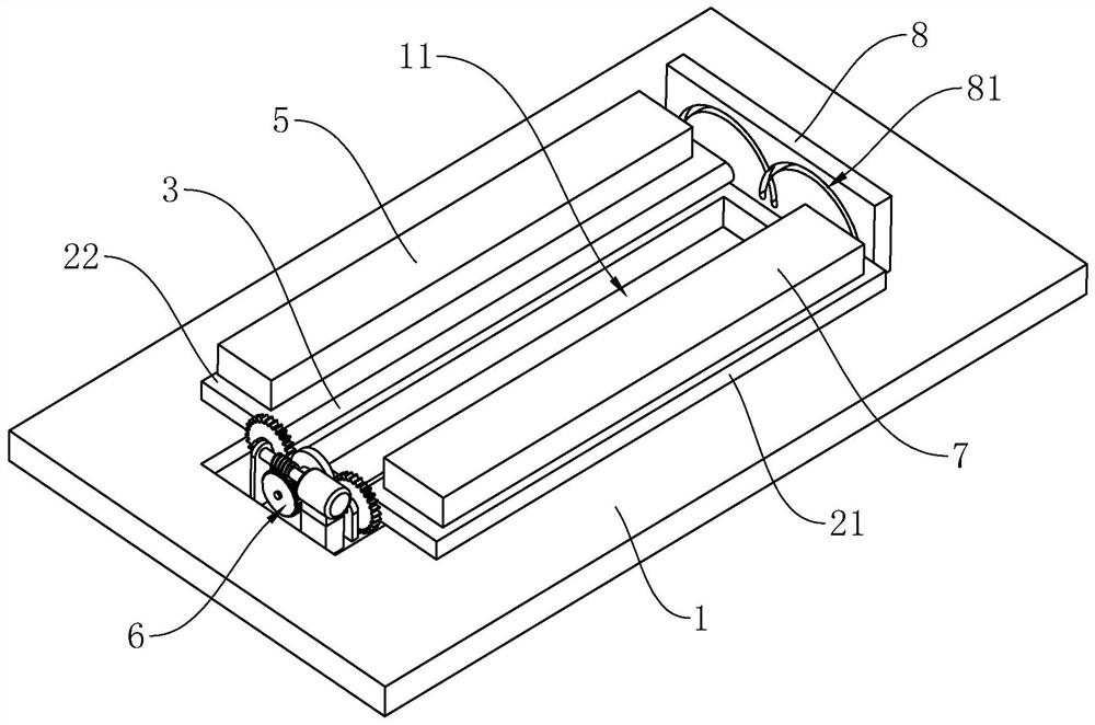
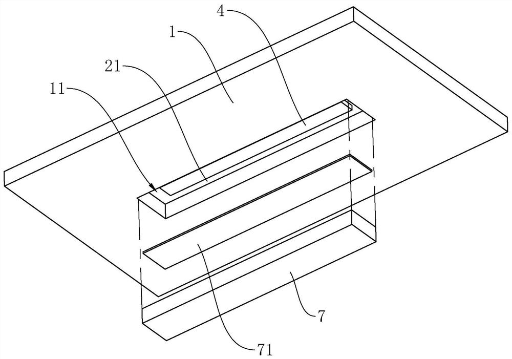
[0042] refer to figure 1 and figure 2 The structure of the ceiling decorative light belt includes a ceiling 1 arranged on the indoor roof. The ceiling 1 is generally installed on the keel of the indoor roof, and can also be installed on the indoor roof by hanging; the ceiling 1 is pre-opened with an installation groove 11. The groove 11 is arranged in a rectangular shape, and the ceiling 1 is provided with two mounting plates 2, the two mounting plates 2 are respectively located on both sides of the width direction of the mounting groove 11, and the mounting plates 2 are arranged along the length direction of the mounting groove 11; One end is fixed with a hinge shaft 3 , and the hinge shaft 3 is rotatably connected with the ceiling 1 so that the mounting plate 2 can rotate on the ceiling 1 .

[0043] refer to figure 2 and image 3, for the convenience of description, one of the mounting plates 2 is set as the first mounting plate 21, and the other mounting plate 2 is set...

Embodiment 2

[0053] The difference between this embodiment and embodiment 1 is: refer to Figure 8 , the driving mechanism 6 includes two transmission gears 66, and the two transmission gears 66 are respectively fixed on the two hinged shafts 3; a rack 67 is arranged below the two transmission gears 66, and the rack 67 is arranged along the width direction of the installation groove 11 set, and the rack 67 is slidably connected to the ceiling 1, and the rack 67 can slide along the width direction of the installation groove 11 on the ceiling 1. One side of the rack 67 is provided with a second drive motor 68, and a second transmission assembly 69 is provided between the second drive motor 68 and the rack 67, and the second drive motor 68 can drive the rack 67 to slide through the second transmission assembly 69. .

[0054] refer to Figure 8 , the two transmission gears 66 can mesh with the rack 67, and the center distance between the two transmission gears 66 is greater than the length o...


PUM


Abstract

The application relates to a ceiling decorative lamp strip structure which comprises a ceiling arranged indoors, a mounting groove is formed in the ceiling in advance, the ceiling decorative lamp strip structure is characterized by further comprising two mounting plates which are arranged above the ceiling and located on the two sides of the mounting groove respectively, and a hinge shaft is fixedly arranged at one end of each mounting plate; the hinge shafts are rotationally connected to the ceiling; one mounting plate is set as a first mounting plate, and the other mounting plate is set as asecond mounting plate; the first mounting plate covers the mounting groove, a lamp strip is arranged on the first mounting plate, and the lamp strip is located in the mounting groove; the second mounting plate abuts against the ceiling, and a decorative plate capable of filling the mounting groove is arranged on the side wall, away from the ceiling, of the second mounting plate; and the structurealso includes a driving mechanism that is arranged on the ceiling and is used for driving the two hinge shafts to rotate. The ceiling decorative lamp strip structure has the effect that the influencedegree of the lamp strip on the attractiveness and cleanliness of the ceiling in the daytime is small.

Description

technical field [0001] The present application relates to the field of ceiling hanging lamps, in particular to a ceiling decorative lamp strip structure. Background technique [0002] In interior decoration, various decorative patterns are usually carved on the ceiling to beautify the interior, and light strips of various colors are also installed on the ceiling for lighting and decoration at night. dual role. At present, the light strips are generally installed directly on the ceiling. During the daytime, the light strips not only fail to provide lighting, but also destroy the integrity of the pattern on the ceiling, making the ceiling less beautiful and tidy. [0003] With regard to the related technologies mentioned above, the inventor believes that there is a defect that the light strip affects the aesthetics and cleanliness of the ceiling during the day. Contents of the invention [0004] In order to improve the influence of the light strip on the aesthetics and cle...

Claims


Application Information

Patent Timeline
Patent Type & Authority Applications(China)
IPC IPC(8): F21S8/02F21V19/00F21V21/15F21V5/08F21V33/00E04B9/00F21Y115/10
CPCF21S8/026F21V19/001F21V21/15F21V5/08F21V33/00E04B9/006F21Y2115/10
Inventor 彭林
Owner 深圳市尚石设计有限公司
Why Eureka
Try Eureka