Clock generating circuit for radio frequency identification (RFID) tag and calibrating method of clock generating circuit

A technology for clock generation circuits and radio frequency identification tags, which is applied to electric pulse generator circuits, record carriers used by machines, instruments, etc., can solve the problems of increased power consumption, decreased recognition distance performance indicators of tag chips, and reduced chip yield, etc. question

Active Publication Date: 2012-09-19
BEIJING TONGFANG MICROELECTRONICS
View PDF3 Cites 24 Cited by
  • Summary
  • Abstract
  • Description
  • Claims
  • Application Information

AI Technical Summary

Problems solved by technology

First of all, the discreteness may cause the code rate size and code rate accuracy returned by the tag to fail to meet the protocol requirements, and may cause errors in the receiving and decoding of the tag, thereby reducing the yield of the chip
In addition, in order to prevent the above problems, the oscillation frequency must be increased. However, if the oscillator works at a higher frequency, its own power consumption and the power consumption of subsequent digital circuits will increase, which will lead to overall chip degradation. Increased power consumption, resulting in a decrease in the recognition distance performance index of the tag chip

Method used


Image

  • Clock generating circuit for radio frequency identification (RFID) tag and calibrating method of clock generating circuit
  • Clock generating circuit for radio frequency identification (RFID) tag and calibrating method of clock generating circuit
  • Clock generating circuit for radio frequency identification (RFID) tag and calibrating method of clock generating circuit

Examples


Embodiment 1

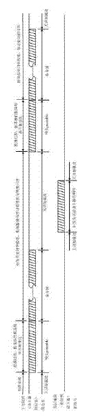
[0089] see Figure 5 , when the oscillator frequency modulation control word Ctrl and the oscillator output frequency f clk When there is a positive correlation, the calibration steps of the self-calibrating clock generation circuit are as follows:

[0090] Passive RF tags enter the RF field of the card reader, the tag power recovery circuit restores the DC power supply voltage on the tag chip, the digitally controlled tuned oscillator starts to oscillate freely, and the reset signal generating circuit generates a power-on reset signal Rst, which is to the The controller and the counter are reset asynchronously, and the frequency modulation control word Ctrl[m-1:0] register of the controller is asynchronously reset to 2 m-1 -1. At this time, the calibration enable signal Calib_en output by the digital baseband processing circuit of the tag is at an invalid level.

[0091] The analog front end of the tag chip demodulates the forward link communication signal from the car...

Embodiment 2

[0101] see Figure 6 , when the oscillator frequency modulation control word Ctrl and the oscillator output frequency f clk When there is a negative correlation, the calibration steps of the self-calibrating clock generating circuit are as follows:

[0102] Passive RF tags enter the RF field of the card reader, the tag power recovery circuit restores the DC power supply voltage on the tag chip, the digitally controlled tuned oscillator starts to oscillate freely, and the reset signal generating circuit generates a power-on reset signal Rst, which is to the The controller and the counter are reset asynchronously, and the frequency modulation control word Ctrl[m-1:0] register of the controller is asynchronously reset to 2 m-1 . At this time, the calibration enable signal Calib_en output by the digital baseband processing circuit of the tag is at an invalid level.

[0103] The analog front end of the tag chip demodulates the forward link communication signal from the card ...


PUM


Abstract

The invention discloses a clock generating circuit for a radio frequency identification (RFID) tag and the calibrating method of the clock generating circuit and relates to the technical field of RFID. The clock generating circuit provided by the invention comprises a numerical control tuned oscillator, a controller, a counter and a digital baseband processing circuit. A demodulation signal Rx output by tag radio frequency is input to the tag digital baseband processing circuit and the controller, and a power-on reset signal Rst output by a reset signal generating circuit arranged at the front end of the tag radio frequency is input to the controller, the counter and the tag digital baseband processing circuit. A calibration-enable signal Calib_en output by the tag digital baseband processing circuit is connected to the input ends of the controller and the counter. The count output Count of the counter is connected to the input end of the controller, and Rst_cnt output by the controller is connected to the input end of the counter. By using the clock generating circuit and the calibrating method thereof, the influences of an integrated circuit manufacturing process, an application environment and temperature on the bit rate precision, the code, the duty ratio and the like of the chip of the RFID tag can be avoided, the power consumption of the chip of the tag can be reduced, and the finished product rate of the chip can be increased.

Description

[0001] technical field [0002] The invention relates to the technical field of radio frequency identification (RFID), in particular to a local clock generating circuit of a radio frequency identification system tag chip and a calibration method thereof. Background technique [0003] Radio Frequency Identification (RFID) is a non-contact automatic identification technology that uses radio frequency signals and spatial coupling transmission characteristics to realize automatic identification of identified targets. RFID systems usually consist of card readers, radio frequency tags and data management systems. According to the different methods of obtaining energy, radio frequency tags can be divided into three types: active electronic tags, semi-active electronic tags and passive electronic tags. Active electronic tags and semi-active electronic tags have a long recognition distance, but because they require micro batteries, they are bulky and costly. Passive electronic tags...

Claims


Application Information

Patent Timeline
Patent Type & Authority Applications(China)
IPC IPC(8): G06K19/077G06K7/00H03K3/02
Inventor 马长明吴行军
Owner BEIJING TONGFANG MICROELECTRONICS
Why Eureka
Try Eureka