Method for coordinately controlling sub road section green wave induction and distribution
A technology of coordinated control and sub-sections, applied in the direction of traffic signal control, etc., can solve the problems that hinder the promotion of "green wave belt" technology, cannot guarantee, miss the green wave passing time, etc.
- Summary
- Abstract
- Description
- Claims
- Application Information
AI Technical Summary
Problems solved by technology
Method used
Image

Examples
Embodiment 1
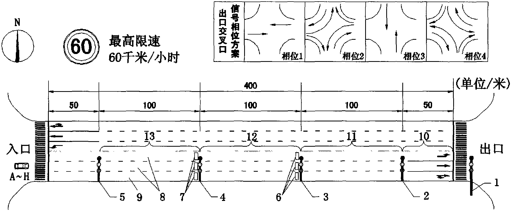
[0058] Such as figure 1 As shown on an east-west main road, a 400-meter-long road section between two intersections from west to east is selected as the research object, then the intersection on the west side of the road section is the entrance intersection, and the intersection on the east side of the road section The mouth is an exit intersection. Set up subsection signal light 1 at 50 meters from the exit stop line, and a 50-meter long section between it and the exit stop line is subsection 1; set up subsection signal light 2 at 150 meters from the exit stop line, which is connected to the exit stop line A 100-meter-long road section between sub-section signal lights 1 is sub-section 2; a sub-section signal light 3 is set up at a distance of 250 meters from the exit stop line, and a 100-meter-long road section between it and sub-section signal lights 2 is Sub-section 3; Finally, a sub-section signal light 4 is set up at 350 meters away from the exit stop line, and a 100-me...
Embodiment 2
[0076] This embodiment discusses whether the coordinated control method described in the present invention can also ensure that green-wave vehicles can run in the "green-wave belt" under complex road conditions.
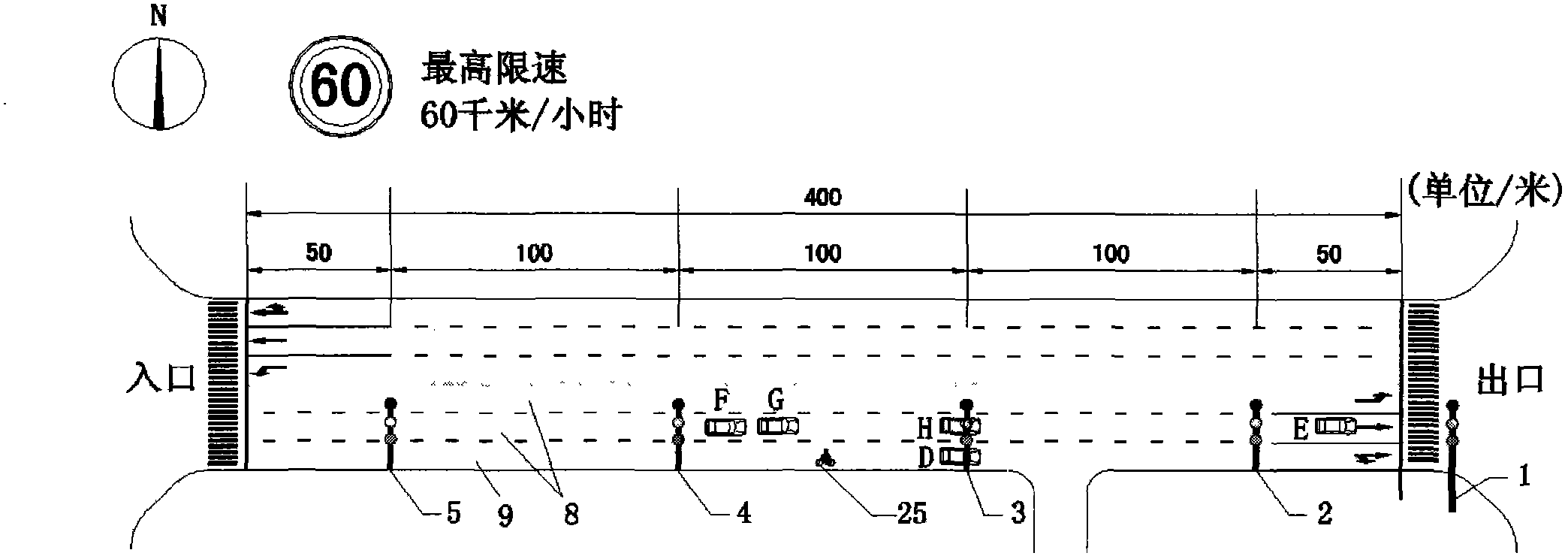
[0077] image 3 The road segment shown in is figure 1 The planar view of the real-time road conditions of the middle road section at t=100 seconds, the difference is that there is an extra fork in the sub-road section 2, and there is a pedestrian 25 crossing the road on the sub-road section 3 at this moment, he will interfere F car, G car normal driving.
[0078] Due to the increase of factors that interfere with the normal driving of green wave vehicles at forks, the speed of green waves on sub-section 2 should be appropriately reduced to reduce the impact of interference factors. Specific measures are as Figure 4 As shown, adjust the phase difference between the signal timing scheme of sub-section signal light 2 and sub-section signal light 1 to O 2 =15 second...
Embodiment 3
[0082] This embodiment illustrates how the coordination control method described in the present invention is combined with the adaptive signal control system to improve its performance. Specifically, how the signal lights of each sub-section change its signal timing scheme in real time according to the real-time traffic conditions collected by the vehicle detector, and how this real-time change has a real-time impact on the driving of green wave vehicles.
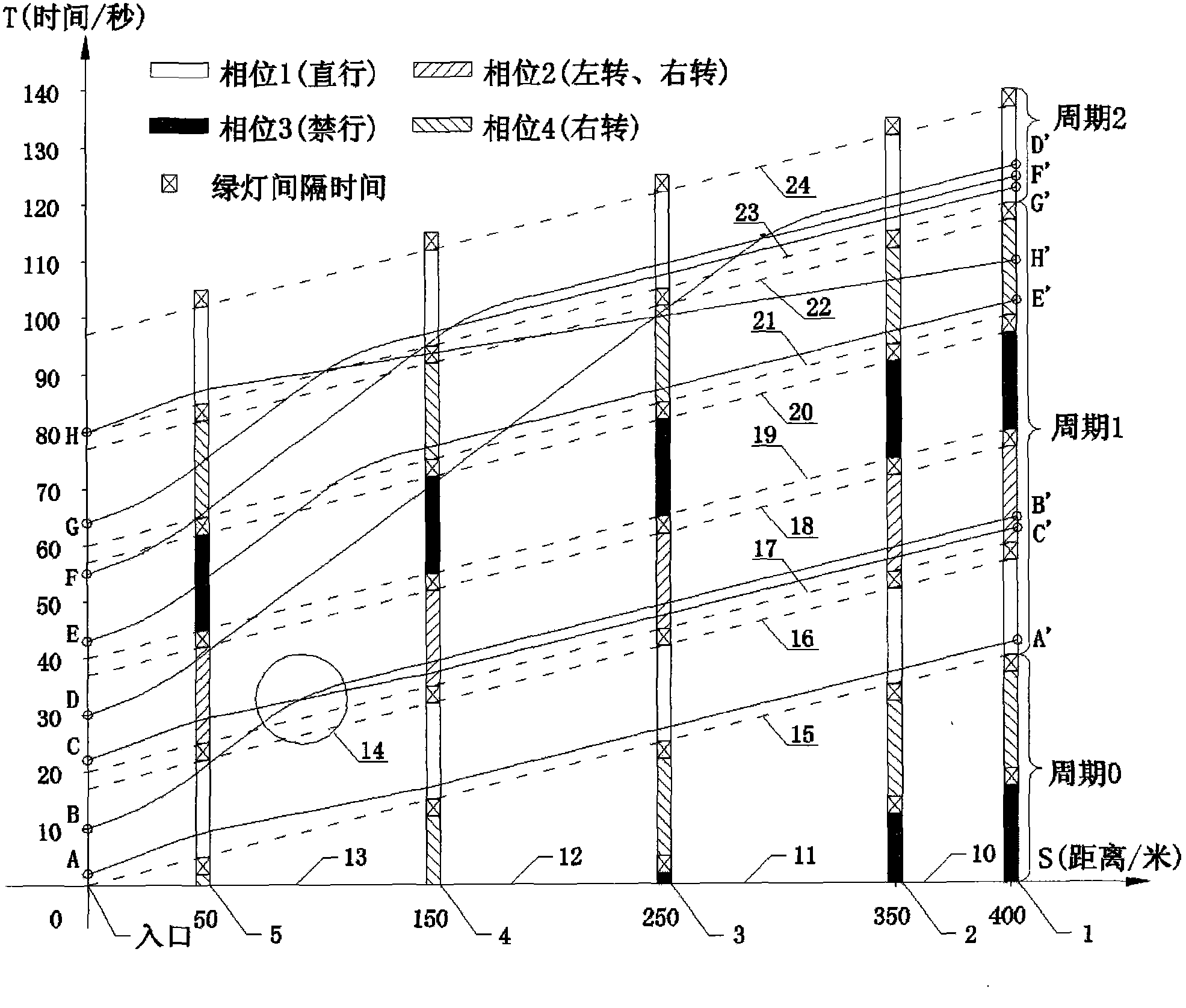
[0083] Such as figure 1As shown, when the vehicle detector 7 detects that the vehicle A passes by, no other vehicles are detected within the set time period of 8 seconds, and the computer adjusts all sub-section signal lights and exit intersections in real time according to this situation. The signal timing scheme of port signal lights. Such as Image 6 As shown, the end time of signal phase 1 of each sub-section signal light is advanced by 4 seconds, and the start time of signal phase 2 of each sub-section signal light i...
PUM
 Abstract
Description
Claims
Application Information
 - Generate Ideas
- Intellectual Property
- Life Sciences
- Materials
- Tech Scout
- Unparalleled Data Quality
- Higher Quality Content
- 60% Fewer Hallucinations
Browse by: Latest US Patents, China's latest patents, Technical Efficacy Thesaurus, Application Domain, Technology Topic, Popular Technical Reports.
© 2025 PatSnap. All rights reserved.Legal|Privacy policy|Modern Slavery Act Transparency Statement|Sitemap|About US| Contact US: help@patsnap.com