
Novel water-proof structure for LED display panel

A technology of LED display panel and waterproof structure, which is applied in the direction of chassis/cabinet/drawer parts, instruments, identification devices, etc. The problems of high rate, man-hour and material cost are high, and the effect of low cost, easy font mode and easy structural assembly is achieved.

Inactive Publication Date: 2012-09-19
蒋晓东
View PDF3 Cites 1 Cited by
  • Summary
  • Abstract
  • Description
  • Claims
  • Application Information

AI Technical Summary

Problems solved by technology

Both of the above two methods use LED transparent cover as the packaging method. The closeness between the transparent cover and the opening of the structural panel is not enough, and water seepage occurs in the pores. Problems such as the peeling of the colloid at low temperature make the surface of the LED display panel installed today have a high failure rate, and the assembly time and material cost are relatively high.

Method used


Image

  • Novel water-proof structure for LED display panel
  • Novel water-proof structure for LED display panel
  • Novel water-proof structure for LED display panel

Examples


Embodiment 1

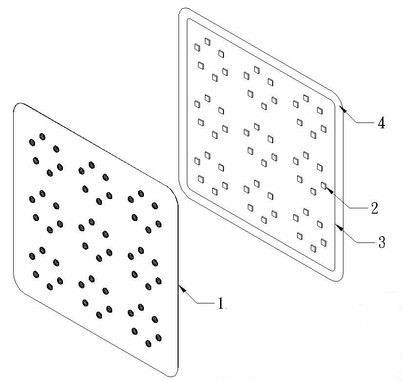
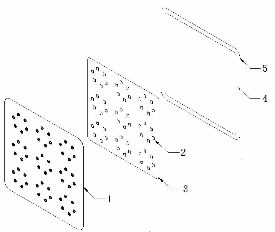
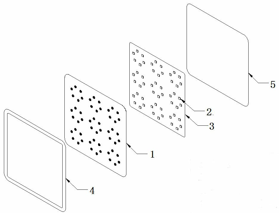
[0023] Embodiment 1: As shown in the figure, this structure is composed of plastic shell 1, LED 2, circuit board 3, pressing parts 4 and back plate 5. Plastic shell 1 is made of transparent plastic shell, and the plastic shell is made by vacuum forming, which can make large The surface area of ​​the board completely covers the LED2 and the circuit board 3, replacing the transparent cover of the LED. At the same time, the emission angle of the LED 2 only needs to be selected from a different LED 2. The vacuum forming mold is much cheaper than the plastic injection mold, and can be produced at the same time. Large area circuit board 3 boards, 300cm x 900cm.

[0024] The transparent plastic shell is made of PET (2. polyethylene terephthalate polyethylene terephthalate), a material with good weather resistance. At the same time, the thickness of the plastic shell 1 depends on the size of the circuit board 3 and the shape of the LED 2. Different thicknesses from 0.3mm to 1.5mm can ...


PUM

PropertyMeasurementUnit
Thicknessaaaaaaaaaa

Abstract

The invention relates to a water-proof structure for an LED display panel. The water-proof structure consists of a rubber shell, LEDs, a circuit board, a press-in piece and a back panel, wherein the LEDs are fixed on the circuit board; the circuit board is positioned between the rubber shell and the back panel; and the press-in piece is arranged at the peripheral connection part of the rubber shell, the circuit board and the back panel. According to the invention, the vacuum-formed rubber shell completely wraps the LED circuit board to fully play a waterproof role, and meanwhile, the assembly and die costs are considerably lowered.

Description

technical field [0001] The invention relates to a waterproof structure of an LED display board. Background technique [0002] The known production and processing methods of LED display panels include the use of light boxes or thin plate interlayers. The light box method is mainly based on the box body, opening holes on the panel, installing the LED transparent cover, and then installing the LED circuit board, or inserting the LED into the transparent cover to connect with wires, and then cover the back panel. The thin plate interlayer method is to open holes on the structural panel, install the LED transparent cover, and place the LED circuit board, back plate or adhesive film. Both of the above two methods use LED transparent cover as the packaging method. The closeness between the transparent cover and the opening of the structural panel is insufficient, and water seepage occurs in the pores. The expansion and contraction of the air in the box will easily suck water dropl...

Claims


Application Information

Patent Timeline
IPC IPC(8): G09F9/33H05K5/02
Inventor 蒋晓东王勉衡
Owner 蒋晓东
Learn More