
Broadband dual-polarized radiation unit and antenna

A dual-polarized antenna and radiation unit technology, applied in the field of communication, can solve problems such as large projection area, severe performance impact, and inconvenient use in practice, and achieve the effects of reducing projection area, improving technical parameters, and reducing weight

Active Publication Date: 2012-09-19
MOBILE ANTENNA TECH SHENZHEN +5
View PDF9 Cites 15 Cited by
  • Summary
  • Abstract
  • Description
  • Claims
  • Application Information

AI Technical Summary

Problems solved by technology

This design has the following two shortcomings. First, the linear structure of the unit arm makes its projected area larger, and the high-frequency oscillator between the two low-frequency oscillators is coupled by the low-frequency oscillator, which deteriorates the radiation performance in the high-frequency band; Second, since the four balancers are fixed on a fixed seat under the high-frequency vibrator and are closer to the high-frequency vibrator, the impedance and radiation characteristics of the high-frequency vibrator are greatly affected by the low-frequency vibrator
[0004] Since the ratio of the low frequency to the high frequency of the ultra-wideband multi-frequency dual-polarized antenna in the prior art has reached more than three times, and the distance between two adjacent low-frequency vibrators is twice that between two adjacent high-frequency vibrators, in order to ensure high However, due to the large projected area of ​​the low-frequency oscillators, reducing the spacing will have a severe impact on the performance of the high-frequency oscillators between the low-frequency oscillators, thereby affecting the electrical performance of the entire multi-frequency antenna. Performance
[0005] In summary, the existing ultra-wideband multi-frequency dual-polarized antenna obviously has inconvenience and defects in actual use, so it is necessary to improve it

Method used


Image

  • Broadband dual-polarized radiation unit and antenna
  • Broadband dual-polarized radiation unit and antenna
  • Broadband dual-polarized radiation unit and antenna

Examples


Embodiment Construction

[0026] In order to make the object, technical solution and advantages of the present invention clearer, the present invention will be further described in detail below in conjunction with the accompanying drawings and embodiments. It should be understood that the specific embodiments described here are only used to explain the present invention, not to limit the present invention.

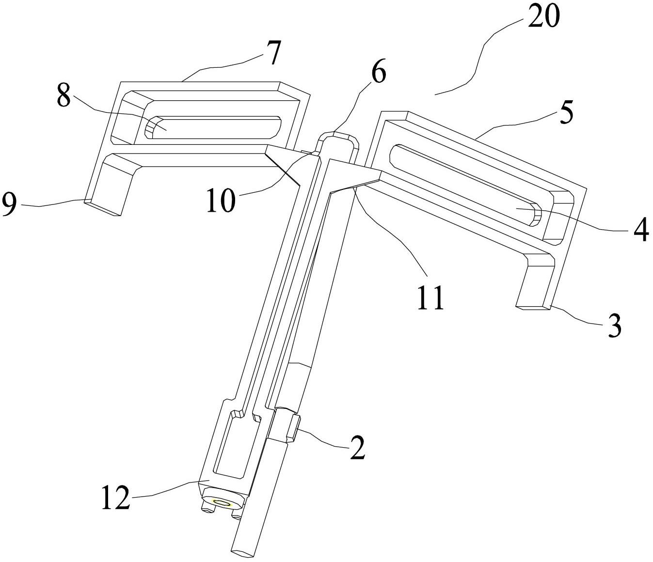
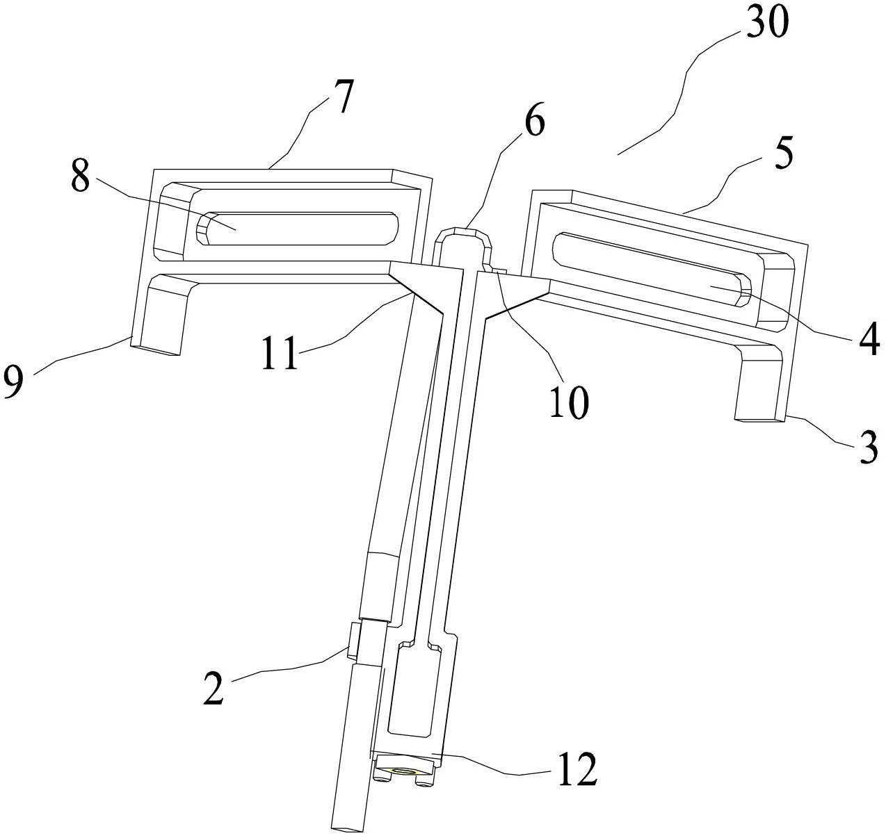
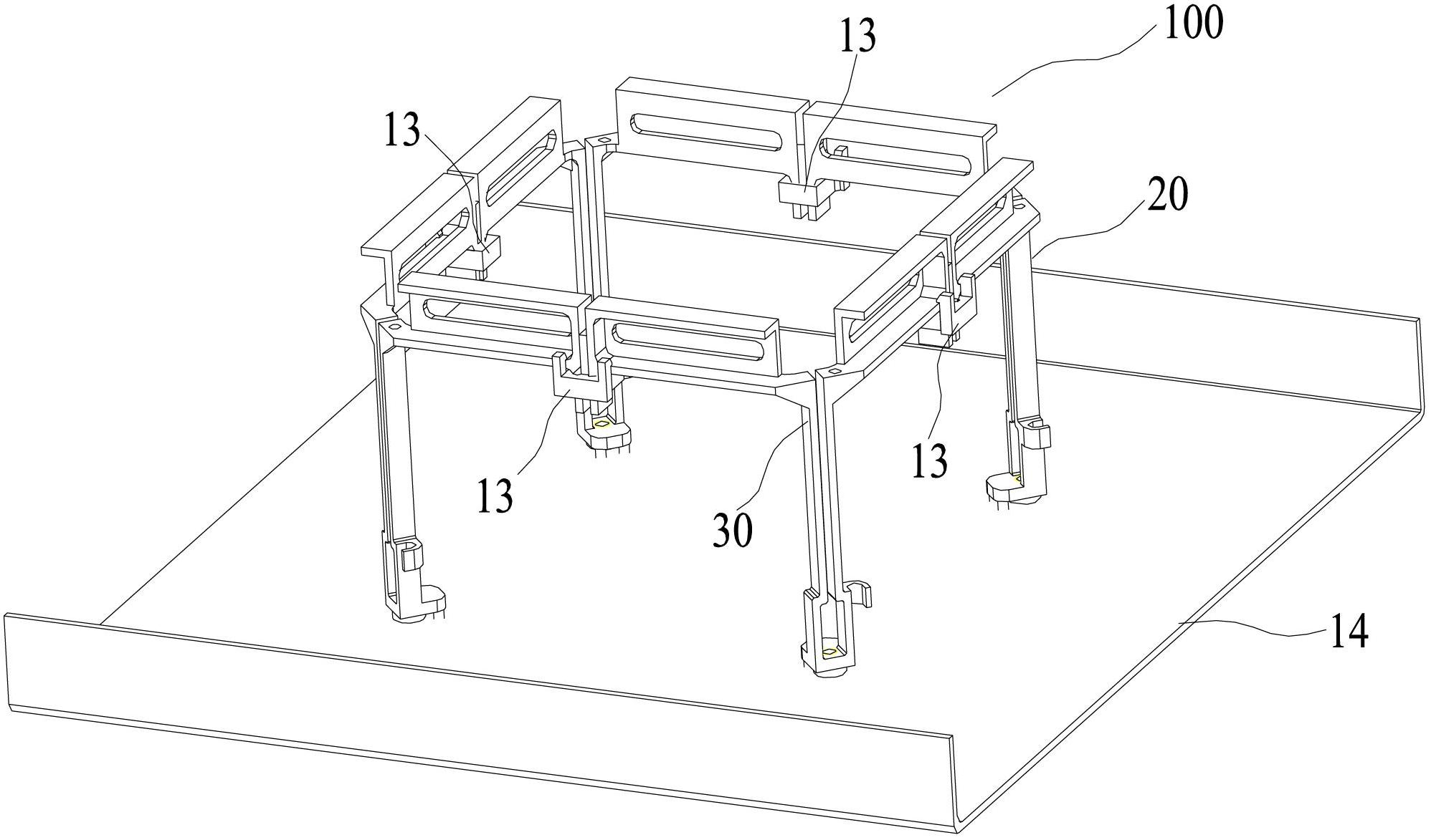
[0027] see figure 1 , the present invention provides an antenna element, the first antenna element 20 and figure 2 The illustrated second antenna element 30 has orthogonal polarizations, and several pairs of orthogonally polarized first antenna elements 20 and second antenna elements 30 can form a dual-polarization radiation unit 100. Specifically, the first antenna element 20 includes The base 12, the balanced feed connector 6 and the two unit arms 5 and 7, wherein:

[0028] The balanced feed connector 6 and the two unit arms 5 and 7 are all installed on the base 12. In the embodiment of the pr...


PUM


Abstract

The invention is applicable to the technical field of communication and provides a broadband dual-polarized radiation unit which is arranged on a metal reflection plate to form an antenna. The broadband dual-polarized radiation unit comprises at least four antenna vibrators, wherein each antenna vibrator comprises a base as well as a balance feed connector and two unit arms mounted on the base; the two unit arms are symmetrically arranged; one end of each unit arm is connected with the balance feed connector and the other end of each unit arm is closed and vertically extends to form a convex wall; and the unit arms of the four antenna vibrators are fixedly connected through isolation fixing pieces. The invention further correspondingly provides a dual-polarized antenna comprising a plurality of the radiation units.. Therefore, the size of a multi-frequency common antenna can be reduced; and meanwhile, each technological parameter of the antenna is improved.

Description

technical field [0001] The invention relates to the technical field of communication, in particular to a broadband dual-polarization radiation unit and an antenna. Background technique [0002] At present, under the coexistence of 2G and 3G networks, there are more and more demands for multi-frequency antennas compatible with 2G and 3G networks, and with the rapid development of communication technology, the bandwidth, size and performance indicators of multi-frequency antennas are also increasing. Make higher and higher demands. [0003] In view of the above development trend, it is more common in the market to adopt two pairs of dipoles to be distributed orthogonally to form a "◇"-shaped or circular antenna design scheme, such as the scheme given in the patent US6333720B1 of the German Kathrein company as the applicant , the vibrator described in this patent adopts two pairs of dipoles to be placed orthogonally, the unit arm is linear, and the entire vibrator cross-sectio...

Claims


Application Information

Patent Timeline
IPC IPC(8): H01Q1/36H01Q19/17H01Q21/24H01Q21/30
Inventor 史坤郭亚军
Owner MOBILE ANTENNA TECH SHENZHEN
Learn More