
Tunable loop antennas

A loop antenna and antenna technology, which is applied in loop antennas, variable reactance loop antennas, antennas, etc., can solve the problems of antennas with narrow working frequency bands and difficult antenna structures to be installed in small devices

Active Publication Date: 2012-09-19
APPLE INC
View PDF9 Cites 50 Cited by
  • Summary
  • Abstract
  • Description
  • Claims
  • Application Information

AI Technical Summary

Problems solved by technology

However, it is difficult to fit traditional antenna structures into small devices
For example, antennas confined to small volumes tend to exhibit narrower operating frequency bands than antennas implemented in large volumes

Method used


Image

  • Tunable loop antennas
  • Tunable loop antennas
  • Tunable loop antennas

Examples


Embodiment Construction

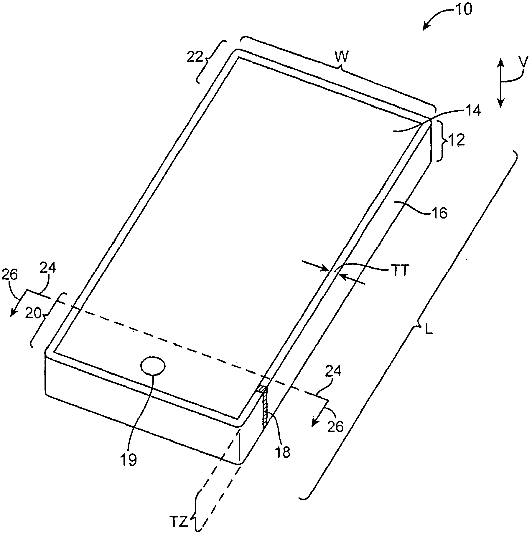
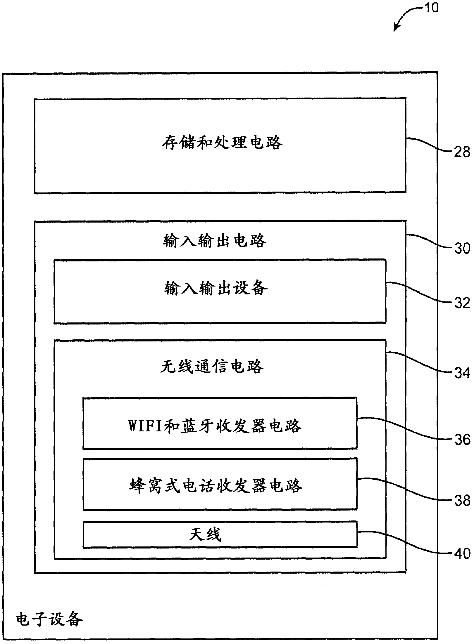
[0032] Electronic devices may be equipped with wireless communication circuitry. The wireless communication circuitry can be used to support wireless communication in multiple wireless communication frequency bands. The wireless communication circuitry may include one or more antennas.

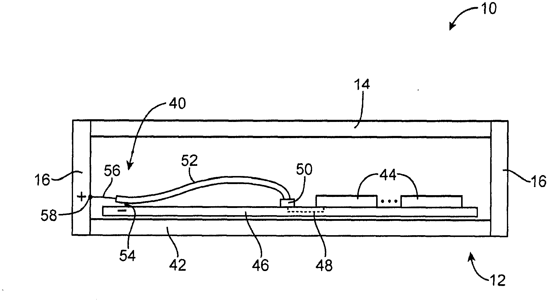
[0033] The antenna may comprise a loop antenna. The conductive structure of the loop antenna may be formed from conductive electronic device structures, if desired. The conductive electronic device structure may include a conductive housing structure. The housing structure may include a conductive frame. A gap structure may be formed in the conductive frame. The antenna may be co-fed using a configuration that helps minimize the antenna's susceptibility to contact with the user's hand or other external objects.

[0034] Any suitable electronic device may be provided with wireless circuitry including loop antenna structures. As an example, loop antenna structures may be used in electronic...


PUM


Abstract

Embodiments of the invention relate to tunable loop antennas. Electronic devices are provided that contain wireless communications circuitry. The wireless communications circuitry may include radio-frequency transceiver circuitry and antenna structures. A parallel-fed loop antenna may be formed from portions of a conductive bezel and a ground plane. The antenna may operate in multiple communications bands. The bezel may surround a peripheral portion of a display that is mounted to the front of an electronic device. The bezel may contain a gap. Antenna feed terminals for the antenna may be located on opposing sides of the gap. A variable capacitor may bridge the gap. An inductive element may bridge the gap and the antenna feed terminals. A switchable inductor may be coupled in parallel with the inductive element. Tunable matching circuitry may be coupled between one of the antenna feed terminals and a conductor in a coaxial cable connecting the transceiver circuitry to the antenna.

Description

[0001] This application claims priority to US Patent Application Serial No. 13 / 041,934, filed March 7, 2011, which is hereby incorporated by reference in its entirety. technical field [0002] The present invention relates generally to wireless communication circuits, and more particularly to electronic devices having wireless communication circuits. Background technique [0003] Electronic devices, such as handheld electronic devices, are becoming more and more popular. Examples of handheld devices include handheld computers, cellular phones, media players, and hybrid devices that include the functionality of multiple devices of this type. [0004] Devices such as these are often equipped with wireless communication capabilities. For example, an electronic device may use long-range wireless communication circuitry such as cellular telephone circuitry for communication using cellular telephone frequency bands at 850 MHz, 900 MHz, 1800 MHz, and 1900 MHz (eg, the primary Glob...

Claims


Application Information

Patent Timeline
Patent Type & Authority Applications(China)
IPC IPC(8): H01Q7/00H01Q1/50H01Q1/44H01Q1/22H01Q5/01H01Q5/10
CPCH01Q7/005H01Q1/243H01Q7/00
Inventor 金男波M·帕斯科林尼M·A·莫R·W·斯科卢巴R·卡巴勒罗
Owner APPLE INC
Learn More