Circuit and control method thereof

A circuit and inductance technology, applied in the field of circuit and its control, can solve the problems of B-phase inductance L2 and switch tube limitation, and achieve the effect of increasing ripple frequency and reducing ripple

Active Publication Date: 2014-09-03
HUAWEI DIGITAL POWER TECH CO LTD
View PDF4 Cites 0 Cited by
  • Summary
  • Abstract
  • Description
  • Claims
  • Application Information

AI Technical Summary

Problems solved by technology

[0018] In battery mode, B-phase induc

Method used


Image

  • Circuit and control method thereof
  • Circuit and control method thereof
  • Circuit and control method thereof

Examples


Embodiment Construction

[0044] An embodiment of the present invention provides a circuit, which can be applied to a UPS power supply circuit. The following examples are given to describe the present invention in detail.

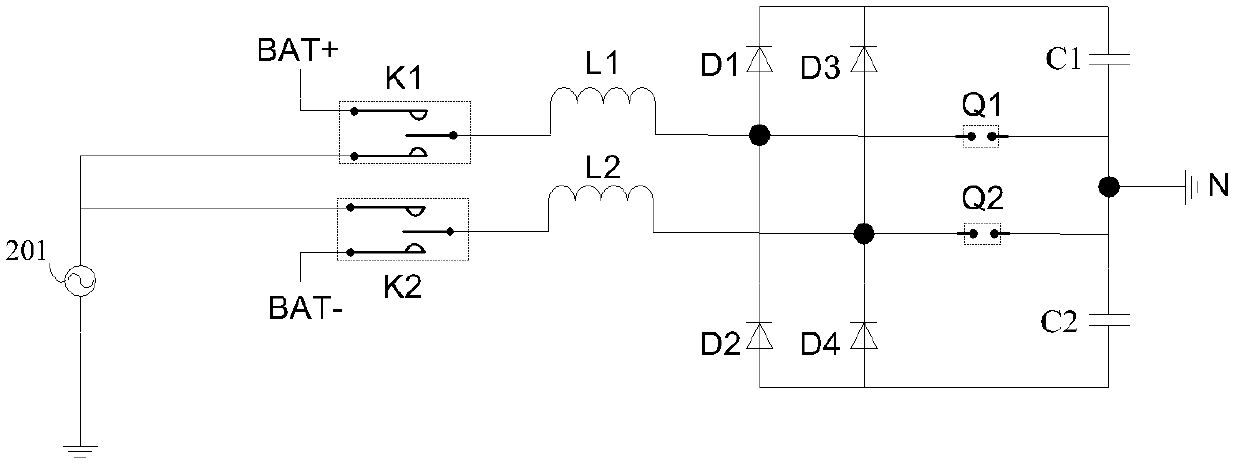
[0045] A circuit in the embodiment of the present invention can be referred to figure 2 , including two bridge arm units and two capacitors, the two bridge arm units are respectively a first bridge arm unit and a second bridge arm unit, and the two capacitors are respectively a first capacitor and a second capacitor.

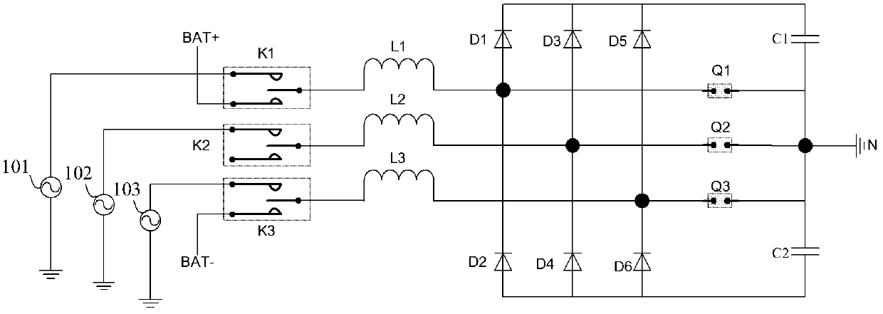
[0046] Each bridge arm unit includes two diodes, an inductor and a switch tube, the two diodes are the first diode and the second diode, the anode of the first diode is connected to the The cathode of the second diode, the junction of the first diode and the second diode are respectively connected to the first port of the inductor and the first port of the switch tube, the switch tube The second port of the second diode is connected to the neutral line N; the catho...


PUM


Abstract

The invention discloses a circuit, which comprises a first bridge arm unit, a second bridge arm unit, a first capacitor and a second capacitor. Second ports for inductors of the first bridge arm unit and the second bridge arm unit are used for inputting cophase alternate current. Switch tubes of the first bridge arm unit and the second bridge arm unit are opened in a staggered manner to charge a first inductor and a second inductor, and the capacitance ripple waves are reduced. Under a working mode of a battery, the first bridge arm unit and the second bridge arm unit can still charge the inductors, and the circuit is not provided with idle devices, so as to improve the utilization ratio of the devices.

Description

technical field [0001] The invention relates to a circuit and a control method thereof. Background technique [0002] A three-phase Vienna (Vienna) power factor correction (PFC, Power Factor Correction) circuit is widely used in an inverter circuit of an uninterruptible power supply (UPS, Uninterruptible Power System). Such as figure 1 As shown, the three-phase Vienna PFC circuit generally used in UPS mainly includes: A phase 101, B phase 102 and C phase 103 of the three-phase AC power supply AC, battery positive pole BAT+ and battery negative pole BAT-, selection switches K1, K2 and K3 , inductors L1, L2, and L3, diodes D1, D2, D3, D4, D5, and D6, switches Q1, Q2, and Q3, capacitors C1, C2, and neutral line N, where K1 can be connected to phase A or BAT+ , K2 can choose to connect to phase B or not, and K3 can choose to connect to phase C or BAT-. The mains work of this three-phase Vienna PFC circuit is mainly completed by two positive and negative half-wave Boost circui...

Claims


Application Information

Patent Timeline
IPC IPC(8): H02M7/40
Inventor 刘培国黄伯宁石鹏
Owner HUAWEI DIGITAL POWER TECH CO LTD
Why Eureka
Try Eureka