
Tunable antenna system with receiver diversity

An antenna and antenna ground technology, which is applied to antenna devices with additional functions, resonant antennas, and components of resonant antennas, etc., can solve the problems of antenna structure fitting into small devices and narrow operating bandwidth.

Active Publication Date: 2015-04-22
APPLE INC
View PDF13 Cites 0 Cited by
  • Summary
  • Abstract
  • Description
  • Claims
  • Application Information

AI Technical Summary

Problems solved by technology

However, it can be difficult to fit conventional antenna structures into small devices
For example, antennas constrained to small volumes typically exhibit narrower operating bandwidths than antennas implemented in larger volumes

Method used


Image

  • Tunable antenna system with receiver diversity
  • Tunable antenna system with receiver diversity
  • Tunable antenna system with receiver diversity

Examples


Embodiment Construction

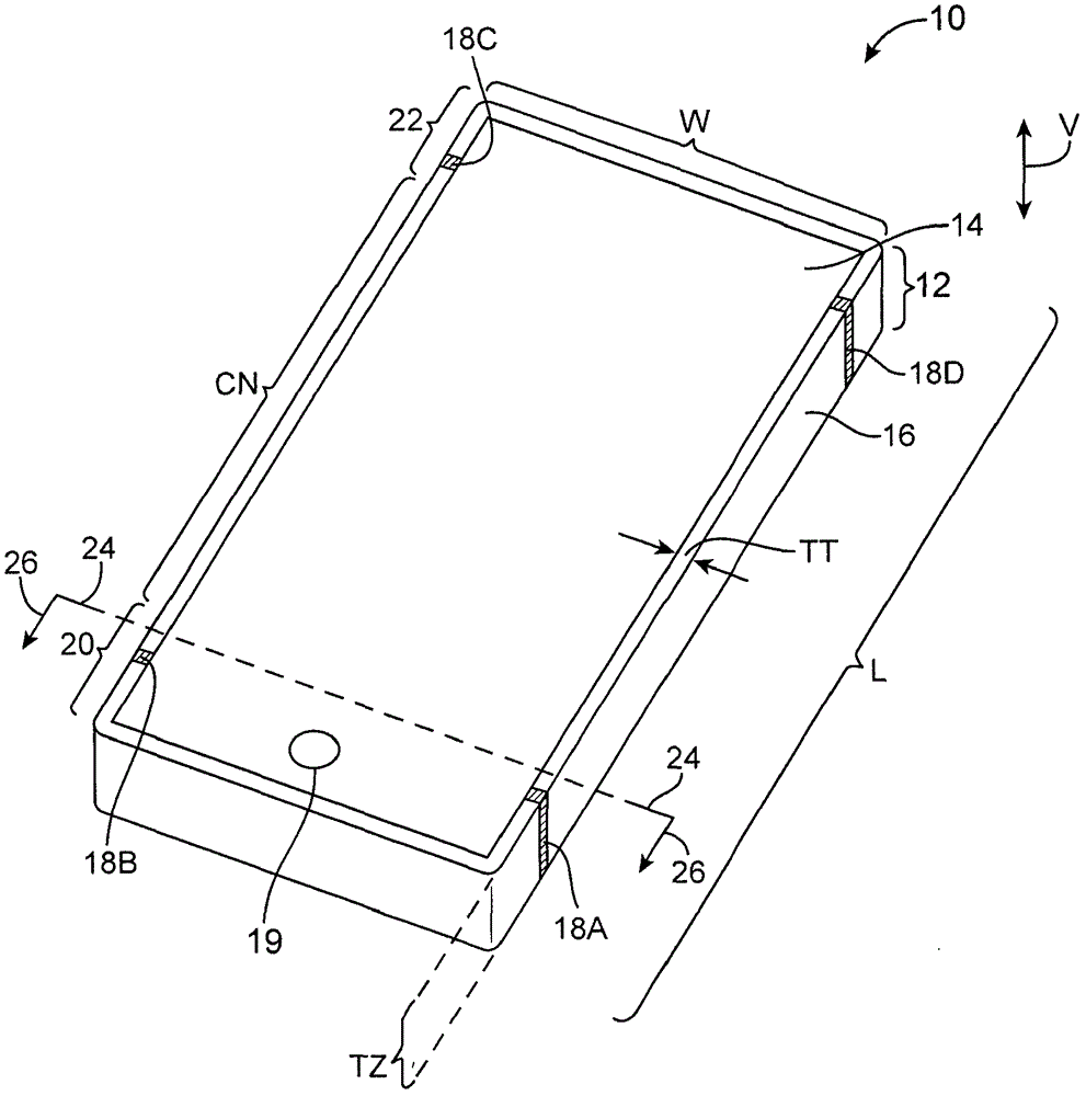
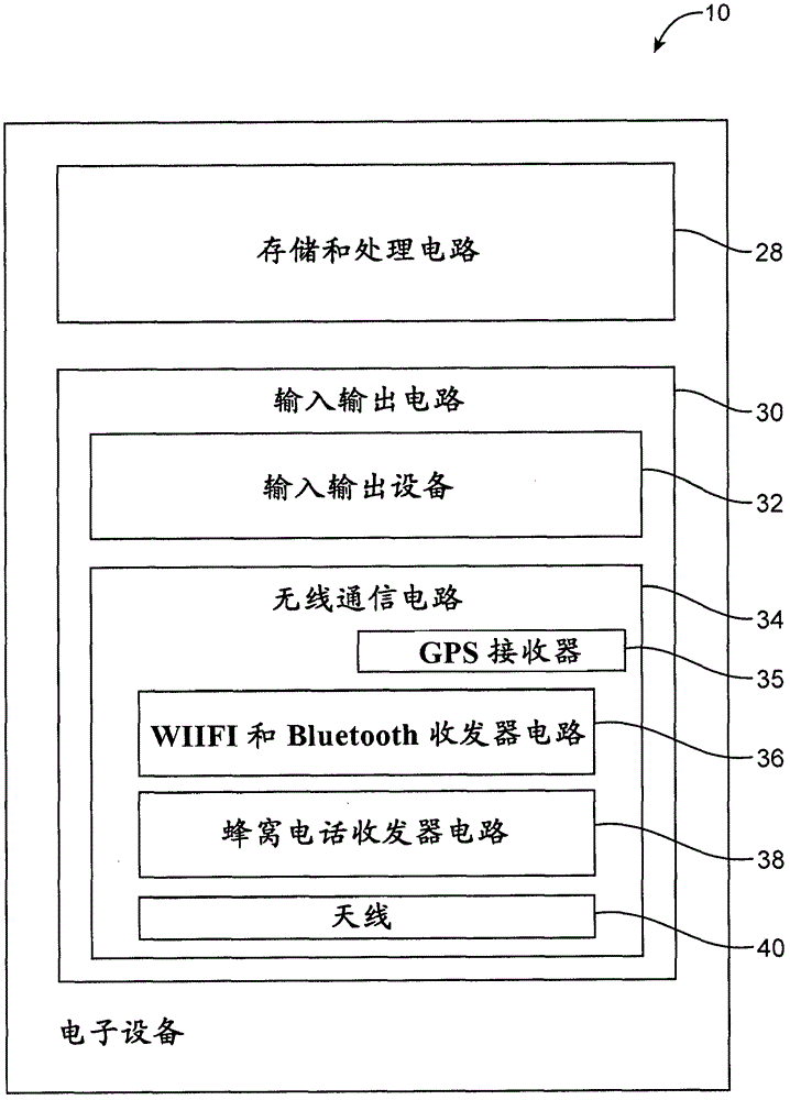
[0024] The electronic device can be provided with a wireless communication circuit. The wireless communication circuit can be used to support wireless communication in multiple wireless communication frequency bands. The wireless communication circuit may include one or more antennas.

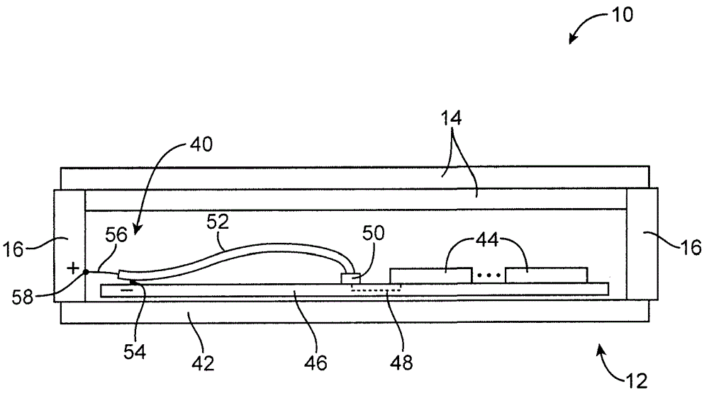
[0025] The antenna may include a loop antenna, an inverted F antenna, a strip antenna, a planar inverted F antenna, a slot antenna, a hybrid antenna including more than one type of antenna structure, or other suitable antennas. If desired, a conductive electronic device structure can be used to form a conductive structure for the antenna. The conductive electronic device structure may include a conductive housing structure. The housing structure may include peripheral conductive components extending around the periphery of the electronic device. The peripheral conductive member may serve as a bezel for a planar structure such as a display, may serve as a side wall structure of a device housing,...


PUM


Abstract

A wireless electronic device (10) may include antenna structures (40U) and antenna tuning circuitry. The device (10) may include a display (14) mounted within a housing (12). A peripheral conductive member (16) may run around the edges of the display and housing. Dielectric-filled gaps (18C) may divide the peripheral conductive member (16) into individual segments (16-1, 16-2). A ground plane (G) may be formed within the housing. The ground plane (G) and the segments (16-1, 16-2) of the peripheral conductive member (16) may form antennas in upper and lower portions of the housing (12). The antenna tuning circuitry may include switchable inductor circuits (210') and variable capacitor circuits (212-1) for the upper and lower antennas. The switchable inductor circuits (210') associated with the upper antenna may be tuned to provide coverage in at least two high-band frequency ranges of interest, whereas the variable capacitor circuits (212-1) associated with the upper antenna may be tuned to provide coverage in at least two low-band frequency ranges of interest.

Description

[0001] This application claims the priority of US Patent Application No. 13 / 041,905 filed on March 7, 2011, which is fully incorporated herein by reference. Technical field [0002] This application relates generally to wireless communication circuits, and in particular to electronic devices having wireless communication circuits. Background technique [0003] Electronic devices such as portable computers and cellular phones are generally provided with wireless communication capabilities. For example, the electronic device may use a long-distance wireless communication circuit such as a cellular phone circuit in order to communicate using cellular phone frequency bands of 850 MHz, 900 MHz, 1800 MHz, 1900 MHz, and 2100 MHz. Electronic devices can use short-range wireless communication links to process communications with nearby devices. For example, electronic devices can use 2.4GHz and 5GHz (IEEE802.11) frequency band and 2.4GHz Band communication. [0004] In order to meet cons...

Claims


Application Information

Patent Timeline
Patent Type & Authority Patents(China)
IPC IPC(8): H01Q1/22H01Q1/24H01Q1/44H01Q7/00H01Q9/14H01Q9/42H01Q21/28H01Q5/307H01Q5/10
CPCH01Q21/28H01Q7/00H01Q9/14H01Q5/307H01Q9/42H01Q1/243H01Q1/44H01L2924/19107H01Q21/06H01Q9/04H01Q1/48H04B1/00
Inventor 金男波M·帕斯科林尼M·A·莫R·W·斯科卢巴R·卡巴勒罗
Owner APPLE INC
Learn More