Optical network protection method, optical link switching control device and optical link switching control system

A technology for controlling equipment and optical links, which is applied in the field of optical communication, can solve problems such as faults, inability to protect communication optical ports, and inability to protect multi-channel optical ports, so as to improve protection capabilities and save networking costs

Inactive Publication Date: 2012-09-19
湖北东方星海科技实业有限公司
View PDF15 Cites 18 Cited by
  • Summary
  • Abstract
  • Description
  • Claims
  • Application Information

AI Technical Summary

Problems solved by technology

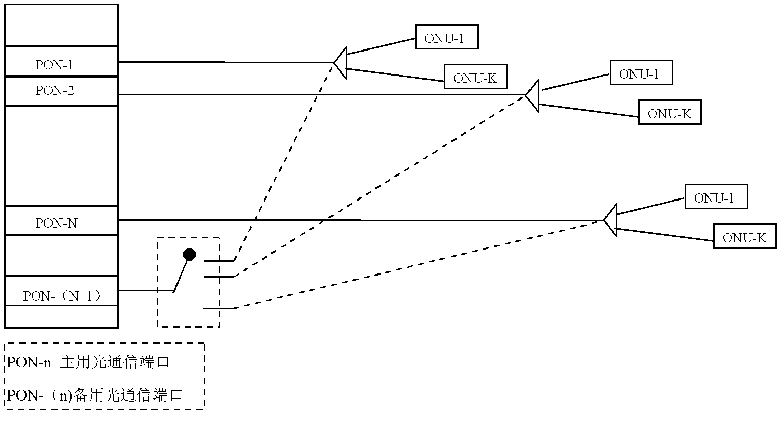
[0004] Chinese patent publication number CN102064885 proposes a "method and device for fast protection switching of PON ports in any slot in 10G-EPON system". This method can only achieve this purpose under the condition of 1:1 redundancy of optical communication ports. In the project, it is difficult to achieve 1:1 redundancy protection for all optical communication ports, and only one port for each port is correspondingly protected. If the protection port fails, the remaining redundant ports cannot protect the communication optical port. protect
[0005] Chinese patent publication number CN101951290A proposes a kind of " EPON optical channel protection technology ", and this method is to provide optical switch at EP

Method used


Image

  • Optical network protection method, optical link switching control device and optical link switching control system
  • Optical network protection method, optical link switching control device and optical link switching control system
  • Optical network protection method, optical link switching control device and optical link switching control system

Examples


Embodiment 1

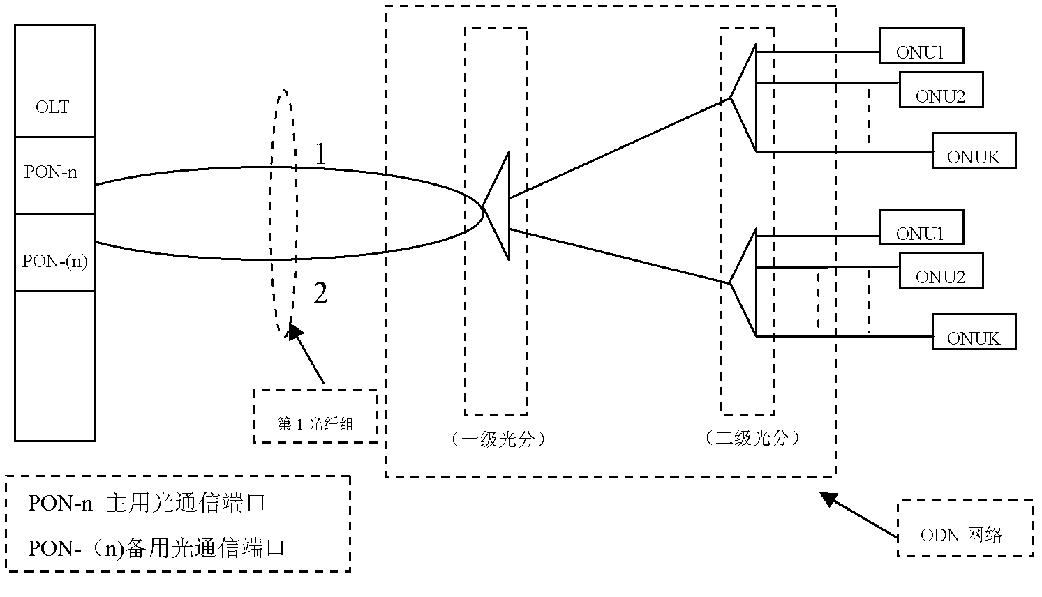
[0074] Embodiment 1. A protection method taking the optical distribution network ODN as an example, the system flow is shown in Figure (4), including:

[0075] A1. The optical link switching control device obtains a related switching request: the switching request is divided into an optical communication port switching request, an optical fiber link switching request, a standby communication switching request, and an optical fiber link monitoring request.

[0076] The switching request may include: main optical communication port information, standby optical communication port information, main optical fiber link information, and standby optical fiber link information.

[0077] In the embodiment of the present invention, when the system related unit learns that the working optical communication port or the working optical fiber link fails, it sends a switching request to the optical link switching control device. It is understandable that the switching request may be sent by the near...

Embodiment 2

[0148] Embodiment 2. A protection method using an optical transmission network as an example. The system flowchart is shown in Figure (16), including:

[0149] B1. The optical link switching control device A receives a switching request: the switching request is divided into an optical communication port switching request, an optical fiber link switching request, an optical communication port connection request, and an optical fiber link connection request.

[0150] The switching request may include: main optical communication port information, standby optical communication port information, main optical fiber link information, and standby optical fiber link information.

[0151] B2. Determine the kind of handover request of the handover request:

[0152] B3: If the switching request is an optical communication port switching request or an optical fiber link switching request, corresponding steps are executed. This process is similar to the related process in Embodiment 1, and is not r...

Embodiment 3

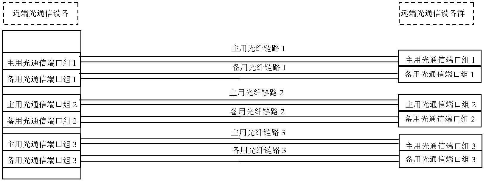
[0201] Embodiment 3. An optical link switching control device. The schematic structural diagram is shown in Figure (6) and Figure (24), including:

[0202] The information transceiver unit is used to receive relevant information of the optical communication system. The relevant information may include: main optical communication port information, standby optical communication port information, main optical fiber link information, standby optical fiber link information, and remote optical communication port information. Communication equipment information, etc.

[0203] In this embodiment, the information transceiving unit is also used to receive a related switching request of the optical communication system; the switching request is divided into: a main optical communication port switching request, a standby optical communication port switching request, and an optical fiber link switching request .

[0204] In this embodiment, the information transceiving unit is also used to send ...


PUM


Abstract

The invention provides an optical network protection method, an optical link switching control device and an optical link switching control system. Multiple optical communication ports are adopted for backups, and simultaneously the system can further provide a multiple-link switching function of optical links. When the system has an optical communication port failure or a line failure, the system selects an appropriate working optical communication port to be connected with a relevant optical link according to relevant information so as to ensure normal communication. In addition, compared with the prior art, a networking mode of multiple masters + multiple standbys + multiple optical links is adopted. When any one group of optical links fails, the system can still provide communication guarantee through an optical link loopback function, thereby greatly improving the protection capability of an optical network system and saving the networking cost. Furthermore, for update and modification of later-stage communication devices, the system can still effectively provide protection, thereby facilitating development of an optical network technology.

Description

Technical field [0001] The invention relates to the field of optical communication technology, in particular to a protection method, optical link switching control equipment and system related to an optical network. Background technique [0002] Optical network is one of the most common networking methods currently used in communication. Because optical fiber has the advantages of bandwidth, large capacity, low loss, and strong anti-interference ability, it has become an indispensable means for communication networks. [0003] However, in the protection of optical networks in the past, protection schemes with more optical communication ports were generally not considered. The current OLT equipment has been able to have 64 PON ports or more. However, the optical distribution network (Optical Distributing Network, ODN) The network structure has exceeded the complexity of the original optical communication network; and the protection of the general optical network has not been conside...

Claims


Application Information

Patent Timeline
IPC IPC(8): H04J14/02H04Q11/00
Inventor 徐志国杨茂富
Owner 湖北东方星海科技实业有限公司
Why Eureka
Try Eureka