
Emergency lamp power supply device

A technology of power supply device and emergency light, which is applied in emergency power supply arrangement, circuit device, electric light circuit arrangement and other directions, can solve the problems of inability to use ordinary lamps, ordinary lamps and lanterns, and is not suitable for use, saving resources, simplifying lines, cost saving effect

Active Publication Date: 2012-09-19
耿波
View PDF3 Cites 17 Cited by
  • Summary
  • Abstract
  • Description
  • Claims
  • Application Information

AI Technical Summary

Problems solved by technology

[0003] 1. The emergency light using the traditional power supply device can only be used as an emergency light (that is, the emergency light is only on when the mains power fails), and cannot be used as an ordinary light
From an economic point of view, it is a huge waste of resources
[0004] 2. Because they cannot be used as ordinary lamps, emergency lights using traditional power sources can only be installed in some public places or departments, such as airports, stations, etc.
However, it is not suitable for public places such as families and communities.
[0005] 3. The detection circuit and switching circuit of the traditional power supply of emergency lights use high energy-consuming devices such as relays, which do not conform to the current energy-saving design concept

Method used


Image

  • Emergency lamp power supply device
  • Emergency lamp power supply device

Examples


Embodiment Construction

[0018] The present invention will be further described below in conjunction with the accompanying drawings.

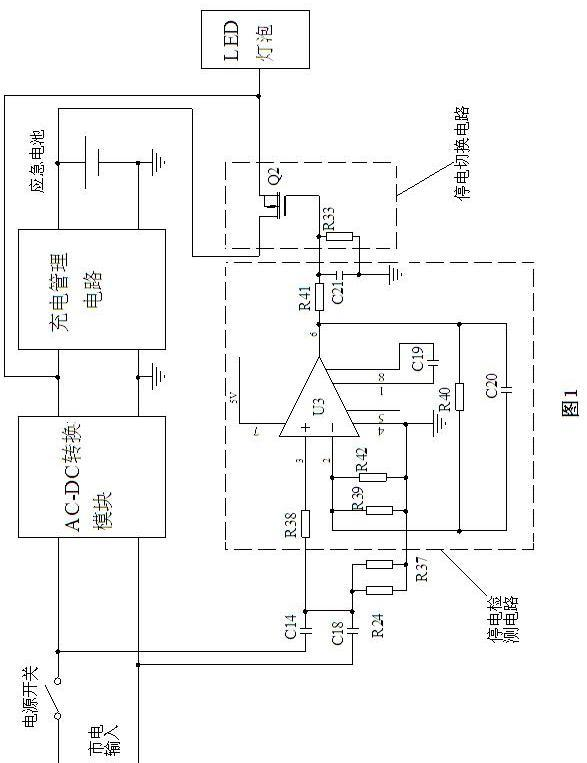
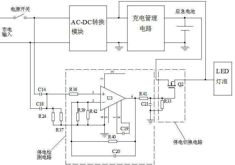
[0019] An emergency light power supply device, which includes: an AC-DC conversion module, a charging management circuit, an emergency battery, a power failure detection circuit and a power failure switching circuit, and the input end of the AC-DC conversion module is connected to the AC mains through a power switch , the output terminals of the AC-DC conversion module are respectively connected with the LED light bulb and the input terminal of the charging management circuit. The emergency batteries are connected in parallel, the two input terminals of the power failure detection circuit are connected to the AC mains through a coupling capacitor, the output terminal of the power failure detection circuit is connected to the input terminal of the power failure switching circuit, and the output terminal of the power failure switching circuit is connected to the emergency...


PUM


Abstract

An emergency lamp power supply device comprises an alternating current-direct current (AC-DC) converting module, a charging management circuit, an emergency battery, a power outage detecting circuit and a power outage switching circuit. The input end of the AC-DC converting module is connected with alternating current mains supply through a power supply switch, and the output end of the AC-DC converting module is respectively connected with a light-emitting diode (LED) bulb and the input end of the charging management circuit. The output end of the charging management circuit is connected with the emergency battery in parallel, two input ends of the power outage detecting circuit are connected with the alternating current mains supply through a coupling capacitor, the output end of the power outage detecting circuit is connected with the input end of the power outage switching circuit, and the output end of the power outage switching circuit is connected with the emergency battery. The emergency lamp power supply device can be used for emergency lighting and also can be used for ordinary lighting, the existing lamp switches and power supply circuits are not required to be changed, and installing and replacement of the emergency lamp power supply device are convenient.

Description

technical field [0001] The patent of the present invention relates to a power supply device for LED emergency lights, in particular to a power supply device for LED lighting that can integrate general lighting and emergency lighting. Background technique [0002] The traditional power supply scheme for emergency lights is: when there is mains power, the emergency light power supply is always in a standby state. When there is a power failure, the relay connects the emergency battery circuit to supply power to the emergency light, and the emergency light is turned on. Emergency lights using this power supply cannot be used as ordinary lamps. The emergency light power supply is converted from AC to DC by an AC-DC converter to charge the emergency battery. In the event of a power failure, the relay connects the emergency battery to supply power to the emergency lamps. The scheme of this emergency light power supply has the following disadvantages. [0003] 1. The emergency li...

Claims


Application Information

Patent Timeline
Patent Type & Authority Applications(China)
IPC IPC(8): H05B37/04H05B44/00
CPCH02J9/065H02J9/00H05B33/0806H05B37/02H05B47/10H05B45/30H02J9/06
Inventor 耿波
Owner 耿波
Learn More