Adiabatic compressed air energy storage system with multi-stage thermal energy storage

A technology for compressing air and compressor systems, applied in the direction of engine functions, gas turbine devices, engine components, etc.

Active Publication Date: 2012-09-19
GENERAL ELECTRIC CO
View PDF6 Cites 13 Cited by
  • Summary
  • Abstract
  • Description
  • Claims
  • Application Information

AI Technical Summary

Problems solved by technology

The presence of such high operating temperatures remains a major obstacle to the implementation of ACAES systems in commercial operations

Method used


Image

  • Adiabatic compressed air energy storage system with multi-stage thermal energy storage
  • Adiabatic compressed air energy storage system with multi-stage thermal energy storage
  • Adiabatic compressed air energy storage system with multi-stage thermal energy storage

Examples


Embodiment Construction

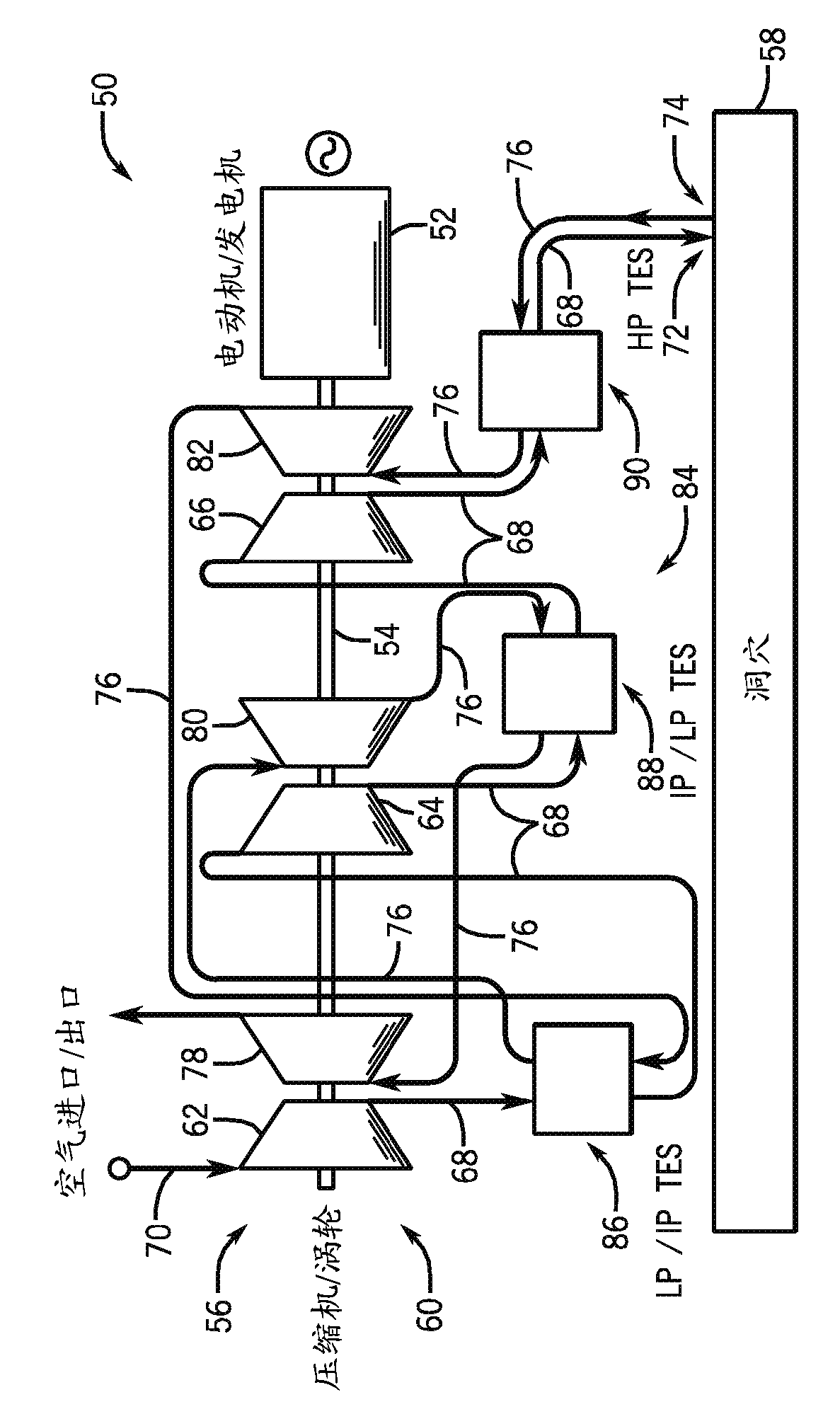
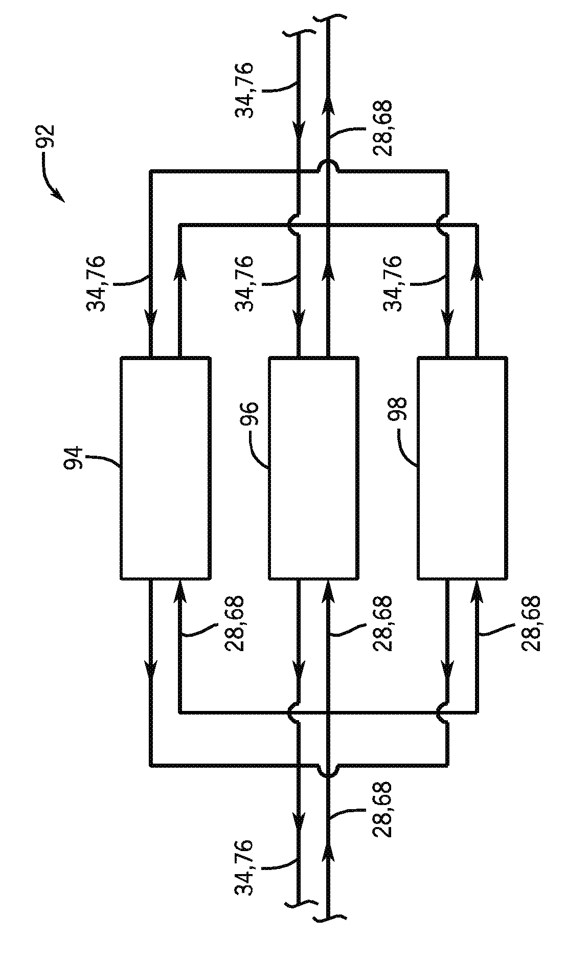
[0019] According to an embodiment of the present invention, a multi-stage thermal energy storage (TES) system is provided to cool and heat air in an adiabatic compressed air energy storage (ACAES) system. A multi-stage TES system includes multiple TES units whose operating states can be switched or reversed between operation of the ACAES system in compression mode and expansion mode.

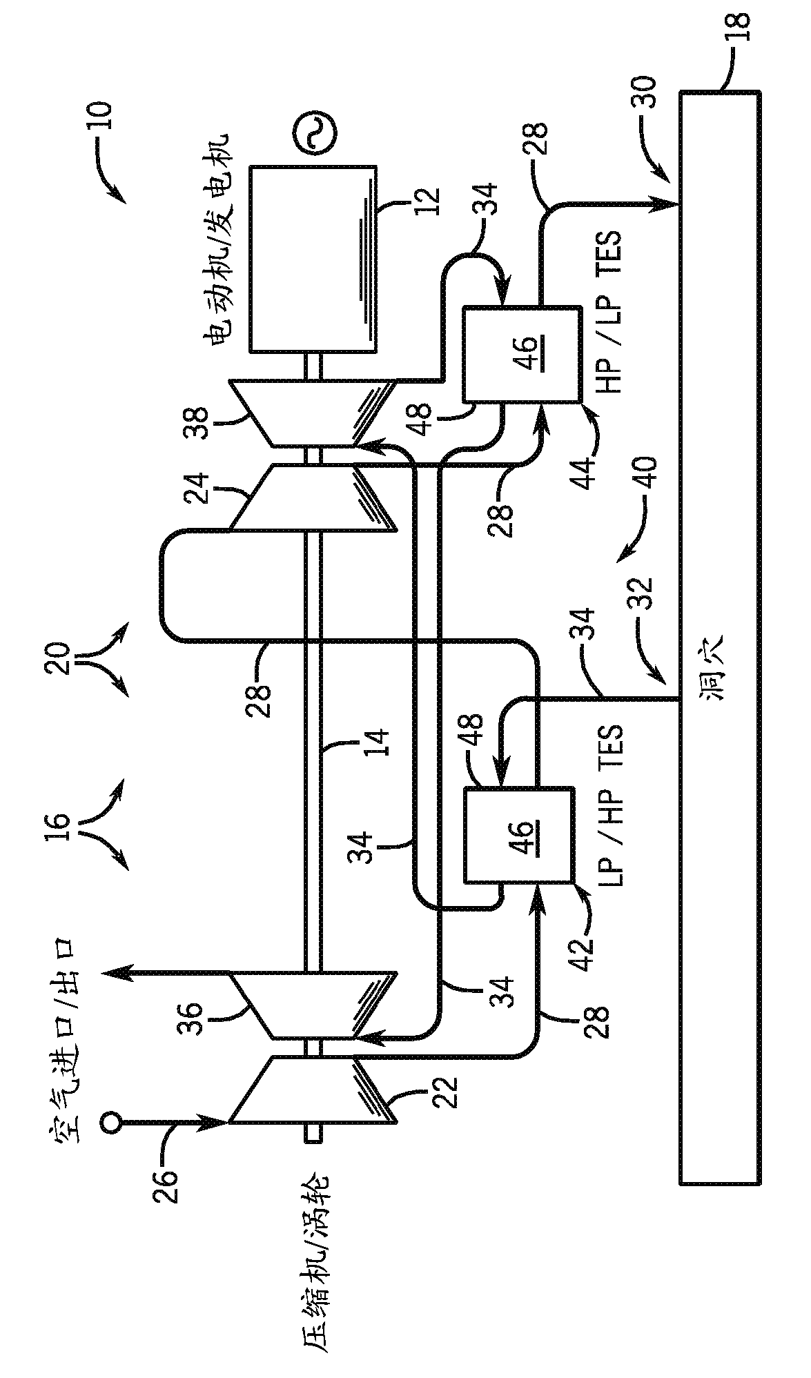
[0020] refer to figure 1 , shows a block schematic diagram of an adiabatic compressed air energy storage (ACAES) system 10 according to one embodiment of the present invention. ACAES system 10 includes motor-generator unit 12 (which may be a combined unit or separate unit), drive shaft 14 , compression system or group 16 , compressed air storage space or cavern 18 , and turbine system or group 20 .

[0021] The motor-generator unit 12 is electrically connected to, for example, a base load power generation device (not shown) to receive power therefrom. Motor-generator unit 12 and drive shaft 14...


PUM


Abstract

An ACAES system operable in a compression mode and an expansion mode of operation is disclosed and includes a compressor system configured to compress air supplied thereto and a turbine system configured to expand compressed air supplied thereto, with the compressor system including a compressor conduit and the turbine system including a turbine conduit. The ACAES system also includes a plurality of thermal energy storage (TES) units positioned on the compressor and turbine conduits and configured to remove thermal energy from compressed air passing through the compressor conduit and return thermal energy to air passing through the turbine conduit. The compressor conduit and the turbine conduit are arranged such that at least a portion of the plurality of TES units operate at a first pressure state during the compression mode of operation and at a second pressure state different from the first pressure state during the expansion mode of operation.

Description

technical field [0001] Embodiments of the present invention relate generally to compressed air energy storage (CAES) systems, and more particularly to multi-stage thermal energy storage (TES) systems in adiabatic CAES systems. Background technique [0002] Air compression and expansion systems are used in a variety of applications across a large number of industries. For example, one such application is to store energy using air compression and expansion systems. Compressed air energy storage (CAES) systems typically include a compression train having multiple compressors that compress intake air and provide the compressed intake air to caverns, underground warehouses, or other compressed air storage sites. The compressed air is then used at a later date to drive a turbine to generate electricity. During operation of the compression stage of a CAES system, the compressed intake air is typically cooled. During operation of the expansion stage, air is exhausted from the und...

Claims


Application Information

Patent Timeline
Patent Type & Authority Applications(China)
IPC IPC(8): F02C6/16F02C1/02
CPCY02E60/15F05D2260/211F05B2260/211F02C6/16F02C1/02F02C1/04Y02E60/16
Inventor S.W.弗罗伊恩德
Owner GENERAL ELECTRIC CO
Why Eureka
Try Eureka