Thermal energy storage system comprising optimal thermocline management

a technology of energy storage system and thermocline, which is applied in the direction of adaptive control, lighting and heating apparatus, instruments, etc., can solve the problems of relative difficulty in maintaining a thermocline in a fluid within a thermal storage tank, degradation of the thermocline in the fluid within the thermal storage tank, and the thermocline degradation becomes more severe, so as to achieve the effect of increasing the temperatur

Inactive Publication Date: 2013-10-08
TERRAFORCE TECH LLC
View PDF11 Cites 14 Cited by
  • Summary
  • Abstract
  • Description
  • Claims
  • Application Information

AI Technical Summary

Problems solved by technology

One shortcoming of thermal energy storage systems is that it is relatively difficult to maintain a thermocline in a fluid within a thermal storage tank.
The process of repeatedly extracting the fluid at a relatively cooler temperature from near the bottom of the tank and returning the fluid at a relatively higher temperature to near the top of the tank increases the width of the transition layer resulting in a degradation of the thermocline in the fluid within the thermal storage tank.
Additionally, thermocline degradation becomes more severe where there is an insufficient amount of thermal energy available.
However, this approach is inefficient, cumbersome, and not operationally practical.

Method used


Image

  • Thermal energy storage system comprising optimal thermocline management
  • Thermal energy storage system comprising optimal thermocline management
  • Thermal energy storage system comprising optimal thermocline management

Examples


Embodiment Construction

[0018]While multiple embodiments of the instant invention are disclosed, still other embodiments may become apparent to those skilled in the art. The following detailed description describes only illustrative embodiments of the invention. It should be clearly understood that there is no intent, implied or otherwise, to limit the invention in any form or manner to that described herein. As such, all alternative embodiments of the invention are considered as falling within the spirit, scope and intent of the disclosure.

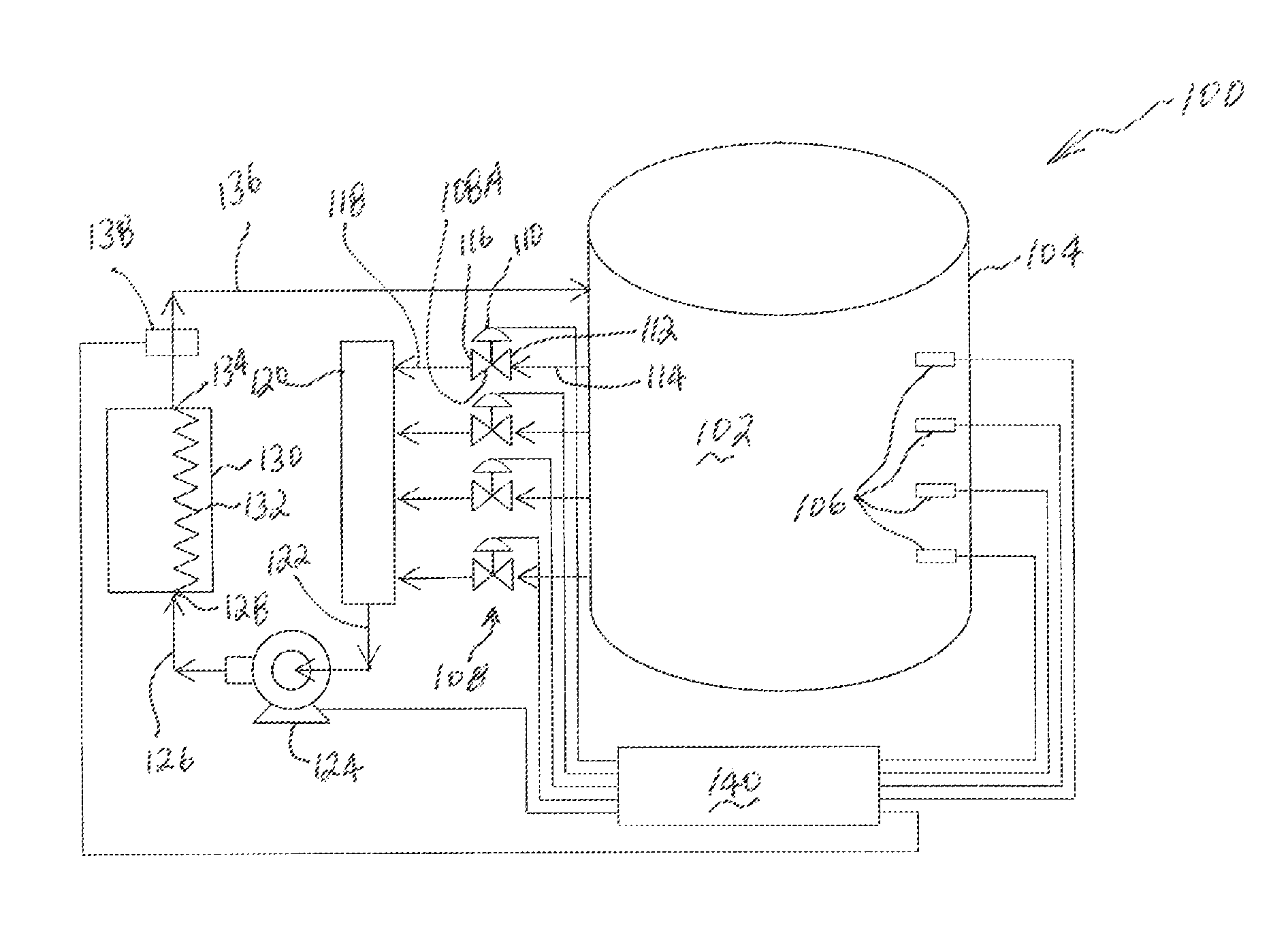
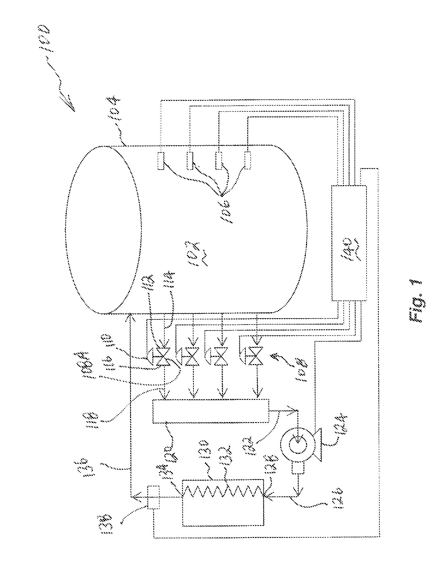
[0019]FIG. 1 is an illustration of thermal energy storage system 100 in accordance with an embodiment of the invention. Thermal energy storage system 100 comprises thermal energy storage fluid 102 contained within thermal energy storage tank 104.

[0020]In an embodiment of the invention, thermal energy storage fluid 102 is a single phase fluid in the form of a liquid which does not undergo a change in phase. In an alternate embodiment of the invention, thermal energy stor...


PUM


Abstract

Methods for optimizing a thermocline in a thermal energy storage fluid within a thermal energy storage tank are disclosed. The methods comprise identifying a thermocline region in the fluid, adding thermal energy to a fluid stream extracted from the thermocline region, and returning the fluid stream to the tank at a plurality of locations above the thermocline region. The methods further comprise regulating the temperature of the fluid returned to the tank at a set point temperature by modulating the flow rate of the fluid stream and by changing the location from where the fluid is extracted from the tank.

Description

TECHNICAL FIELD[0001]The present invention relates to a thermal energy storage system. More specifically, the invention relates to maintaining and optimizing a thermocline in a thermal energy storage fluid contained within a thermal energy storage tank.BACKGROUND[0002]A thermal energy storage system comprises a thermal energy storage fluid contained within a tank. In operation, thermal energy is stored within the fluid by extracting the fluid from the tank, pumping the extracted fluid through a heat exchanger wherein thermal energy in the form of heat is added to the fluid thereby raising its temperature, and returning the heated fluid to the thermal energy storage tank. As is well known in the art, the density of a fluid decreases as the temperature of the fluid increases. As such, a fluid at a relatively lower temperature will have a density which is relatively higher than the density of the same fluid at a relatively higher temperature. Accordingly, the density of the heated flui...

Claims


Application Information

Patent Timeline
Patent Type & Authority Patents(United States)
IPC IPC(8): G05D7/00F28D17/00F28D19/00G05D23/00G05B13/02F28D15/00
CPCF28D20/0039F28D20/02F24J2/345Y02E60/142Y02E60/145F24S60/10F24S60/30Y02E10/40Y02E60/14
Inventor MATHUR, ANOOP KKASETTY, RAJAN B
Owner TERRAFORCE TECH LLC
Why Eureka
Try Eureka