Thermal energy storage in a chiller system

a chiller and energy storage technology, applied in the field of air conditioning systems, can solve the problem of inefficient use of the same chiller system

Active Publication Date: 2017-02-14
CARRIER CORP
View PDF13 Cites 14 Cited by
  • Summary
  • Abstract
  • Description
  • Claims
  • Application Information

AI Technical Summary

Problems solved by technology

Since during daytime operation the chiller is typically operated to provide cooling air at about 55 degrees Fahrenheit in a direct exchange (DX) system, it is inefficient to use the same chiller system to both make ice at 32 degrees Fahrenheit for the ice storage unit and also provide cooling air at the desired supply air temperature during normal operation of the chiller since the two different “lifts” would require different optimization.

Method used


Image

  • Thermal energy storage in a chiller system
  • Thermal energy storage in a chiller system
  • Thermal energy storage in a chiller system

Examples


Embodiment Construction

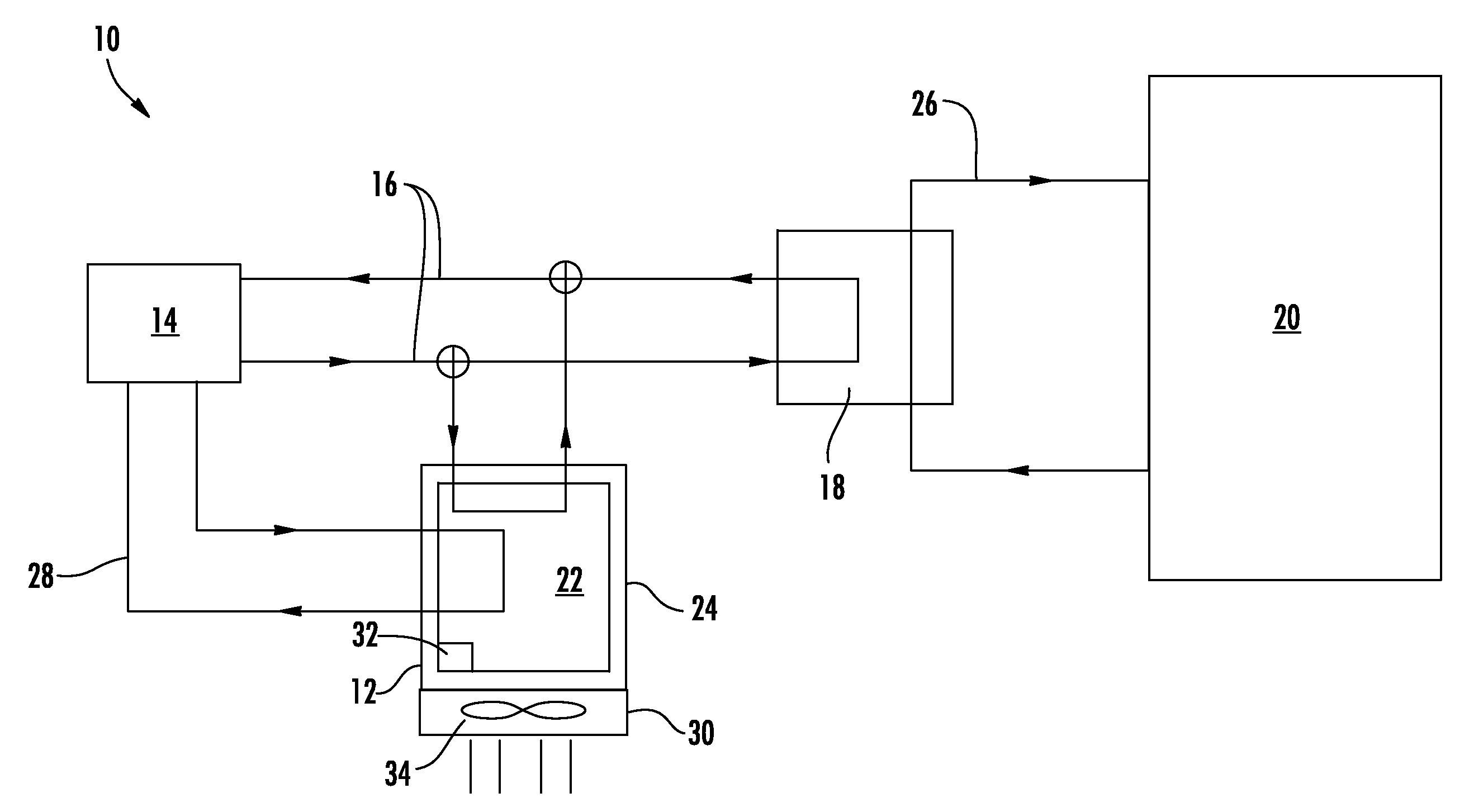
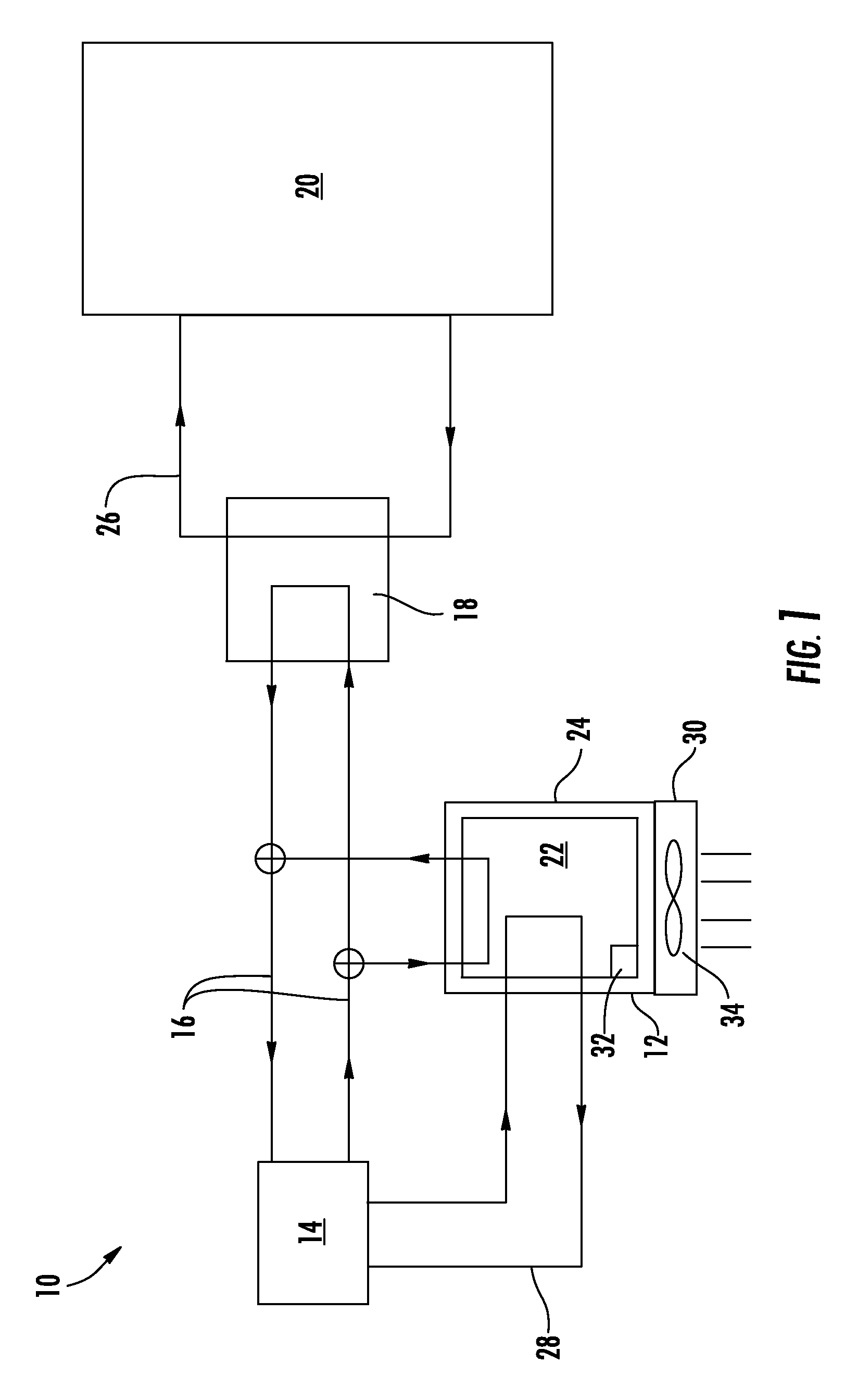
[0012]Shown in FIG. 1 is a schematic of an embodiment of an improved air conditioning system 10 including a thermal energy storage (TES) unit 12. The system 10 illustrated in FIG. 1 is a direct-exchange (DX) system 10. The TES unit 12 is connected to a refrigeration unit, for example, a chiller 14 via one or more refrigerant pathways 16 in which a refrigerant is circulated between the chiller 14 and the TES unit 12. The TES unit 12 is further connected to an evaporator heat exchanger 18, which exchanges thermal energy between a building 20, or other serviced space, and the TES unit 12.

[0013]The TES unit 12 utilizes a volume of phase change material (PCM) 22 to store thermal energy in a storage tank 24. The PCM 22 may be an organic wax material having a transition temperature higher than a typical nighttime temperature, or over about 32 degrees Fahrenheit or zero degrees Celsius, and lower than the typical daytime ambient air. The higher transition temperature of the PCM 22, when com...


PUM


Abstract

A method of operating an air conditioning system includes operating a refrigeration unit to cool a volume of refrigerant and circulating the refrigerant to a heat exchanger. A serviced space is cooled via a thermal energy exchange between the serviced space and the refrigerant at the heat exchanger. Thermal energy generated by operation of the refrigeration unit is stored at a thermal energy storage system. An air conditioning system includes a refrigeration unit and a heat exchanger operably connected to the refrigeration unit. The heat exchanger is configured to transfer thermal energy between a serviced space and the refrigeration unit, thus cooling the serviced space. A volume of thermal energy storage medium is utilized to absorb thermal heat generated by the refrigeration unit for dissipation into the ambient environment at a selected time.

Description

BACKGROUND OF THE INVENTION[0001]The subject matter disclosed herein relates to air conditioning systems. More specifically, the subject disclosure relates to thermal energy storage (TES) systems for air conditioning systems, the commonest forms of which use stored chilled water or ice.[0002]Ice storage is used in air conditioning systems, for example, chiller systems, to take advantage of the large enthalpy content of a volume of frozen water. TES systems that involve a phase change are able to utilize the enthalpy of that phase change in addition to the heat capacity of the medium. A traditional TES system can be used in conjunction with an air conditioning system, for example, a chiller system, to time shift the use of energy by charging and discharging the storage medium, (e.g., ice or water), at different times. For example, the medium can be re-charged during the nighttime by the chiller system when the chiller is not typically needed to cool a space, for example, a building o...

Claims


Application Information

Patent Timeline
Patent Type & Authority Patents(United States)
IPC IPC(8): F25B27/00F25D3/02F25D1/00F24F5/00
CPCF25D1/00F24F5/0021F25D3/02Y02E60/147Y02E60/14
Inventor DOBBS, GREGORY M.
Owner CARRIER CORP
Why Eureka
Try Eureka