Thermal energy storage and plant, method and use thereof

a technology applied in the field of thermal energy storage and plant, method, can solve the problems of reducing limiting the maximum temperature and temperature range, and inefficient or impractical means for charging and discharge of heat, so as to reduce the demand for electric energy grid transfer capacity, increase energy supply security, and increase the maximum electrical consumption

Active Publication Date: 2014-04-24
NEST
View PDF23 Cites 15 Cited by
  • Summary
  • Abstract
  • Description
  • Claims
  • Application Information

AI Technical Summary

Benefits of technology

[0046]Further, the invention provides use of a storage according to the invention, in any embodiment thereof, or a plant according to the invention, in any embodiment thereof, for storage of energy from sources for energy in periods of peak or surplus production or low market price, for delivering said energy in periods of insufficient production or high market price. The use according to the invention results in one or more of the benefits: it reduces the demand for electric energy grid transfer capacity, the energy supply security increases and the maximum electrical consumption can be increased without overloading the grid.
[0047]The invention may also serve an important purpose of providing energy supply security by storage of several types of renewable energy sources such as wind, waves, ocean currents, and solar, which may have rather unpredictable performance of energy delivery. Such energy storage capabilities by the invention may become particularly important in the future as a growing share of the energy supply may be expected to come from renewable sources. It is also worth noting that the invention is well suited in connection with a geothermal heat source which by way of heat storage during the night can increase the power production during the day.

Problems solved by technology

However, inefficient or impractical means for charge and discharge of heat is a typical problem of solid state thermal storages.
The channels add complexity and reduce levels and ranges of stress and displacement that can be handled, thereby limiting the maximum temperature and temperature range, as well as limiting the pressure of the fluid in the channels.
Further, concrete is described as cost effective for thermal heat storage, but all the other elements, including tubes add cost, resulting in a cost for large plants only slightly cheaper than competing technologies.
Achieving a more cost efficient heat storage is set forth as a main challenge; another is to charge and discharge heat more rapidly.

Method used


Image

  • Thermal energy storage and plant, method and use thereof
  • Thermal energy storage and plant, method and use thereof
  • Thermal energy storage and plant, method and use thereof

Examples


Embodiment Construction

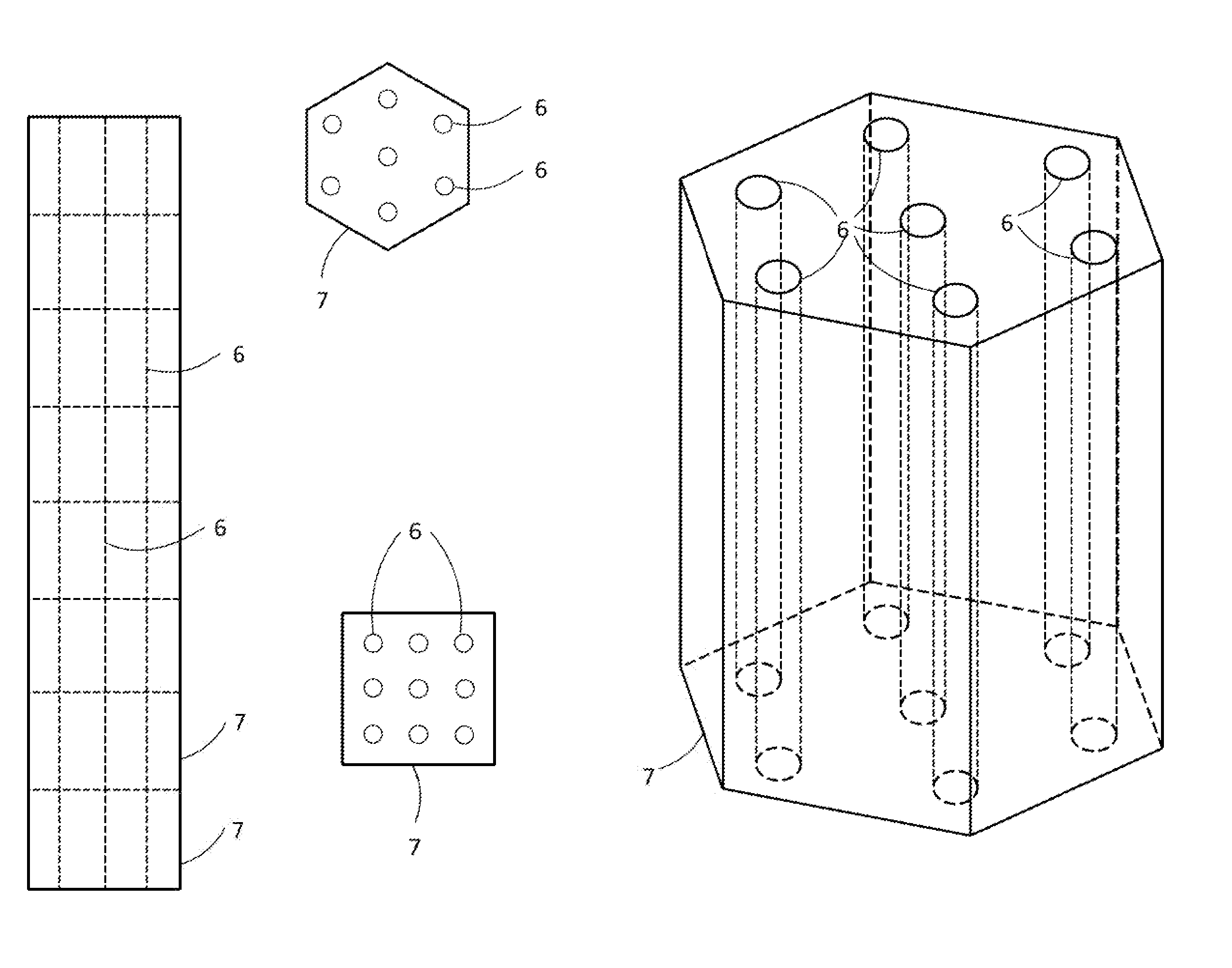
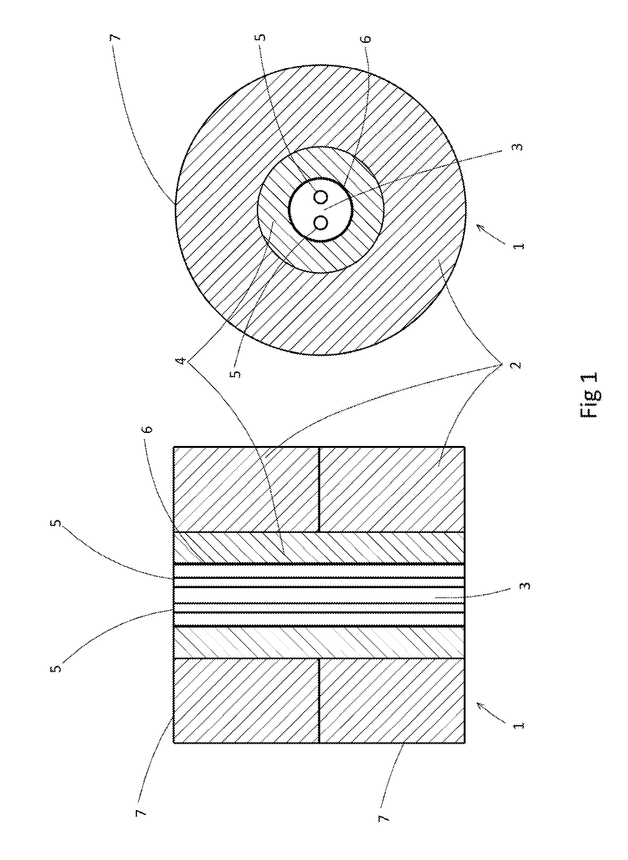
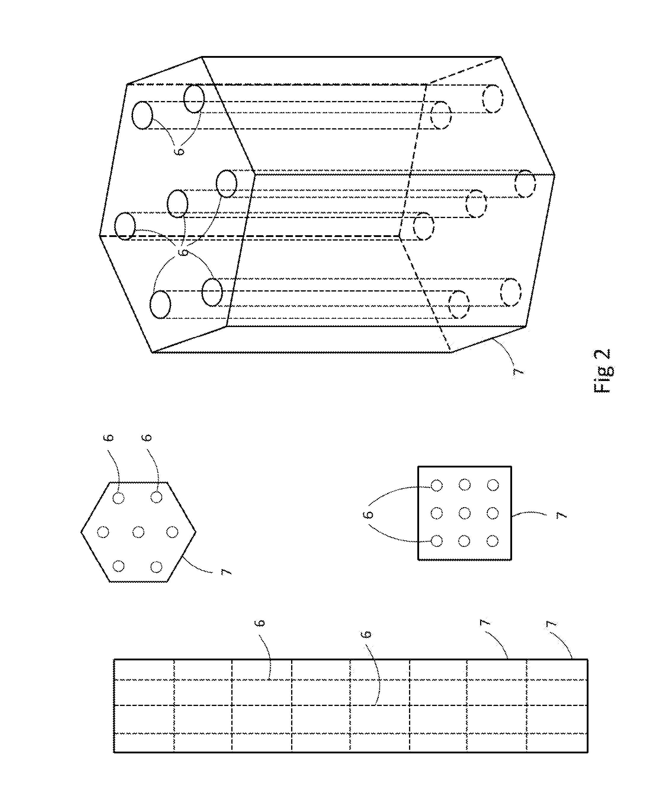
[0060]Reference is made to FIG. 1, illustrating a simple but effective embodiment of a storage of the invention. A thermal energy storage and heat exchange unit 1 is illustrated in longitudinal section and cross section. The storage comprises a solid state thermal storage material 2, 4, more specifically concrete 2 and grouting 4 in the illustrated embodiment, a heat transfer fluid 3 and means for energy input and output 5, that is pressure pipes in the illustrated embodiment. The number of pressure pipes may vary according to the application. The storage further comprises at least one heat transfer container 6, as a section of a cylinder or pipe in the illustrated embodiment. The solid state thermal storage material, grouting 4 and concrete 2, is arranged around the heat transfer container 6. The heat transfer container 6 contains heat transfer fluid 3 and the means for energy input and output 5, so that all heat transferring convection and conduction by the heat transfer fluid tak...


PUM


Abstract

The invention provides a thermal energy storage and heat exchange unit, comprising a solid state thermal storage material, a heat transfer fluid and means for energy input and output, distinctive in that: the storage comprises at least one heat transfer container, solid state thermal storage material is arranged around the heat transfer container, and the heat transfer container contains the heat transfer fluid and the means for energy input and output, so that all heat transferring convection and conduction by the heat transfer fluid takes place within the respective heat transfer container. Method of building the thermal energy storage, plant comprising the storage, method using the plant and use of the storage or plant.

Description

FIELD OF THE INVENTION[0001]The present invention relates to energy storages. More specifically, the invention relates to thermal energy storage and a method of building it, a plant for energy production, a method for energy production and use of the thermal energy storage. The thermal energy storage comprises a solid state main storage.BACKGROUND OF THE INVENTION AND PRIOR ART[0002]Thermal energy storages can be used to store heat when heat is readily available and to deliver heat in periods of demand.[0003]Several solid state heat storages using concrete or natural rock as storage medium are previously known. However, inefficient or impractical means for charge and discharge of heat is a typical problem of solid state thermal storages.[0004]In patent publication DE 10 2009 036 550 A1 a solid state thermal heat storage is described, having a first part A and a second part B. A pipe system for feeding or taking out heat is arranged through the first part A, for charging or dischargi...

Claims


Application Information

Patent Timeline
Patent Type & Authority Applications(United States)
IPC IPC(8): F28D20/00F24S90/00
CPCF28D20/0056Y02E10/40Y02B10/20Y02P90/50F24S60/30Y02E60/14F28D20/00F28D21/00
Inventor BERGAN, PAL
Owner NEST
Why Eureka
Try Eureka