Thermal energy storage system combining sensible heat solid material and phase change material

a technology of energy storage system and sensible heat solid material, which is applied in the direction of heat exchanger types, heat exchange apparatus, regenerative heat exchangers, etc., can solve the problem that the process of obtaining thermal energy is not continuous, and the mechanism of obtaining thermal energy has the limitation of ually, so as to reduce the efficiency of the thermal storage system, reduce the melting point, and increase the effect of inertia

Active Publication Date: 2016-07-14
UNIV POLITECNICA DE CATALUNYA
View PDF2 Cites 14 Cited by
  • Summary
  • Abstract
  • Description
  • Claims
  • Application Information

AI Technical Summary

Benefits of technology

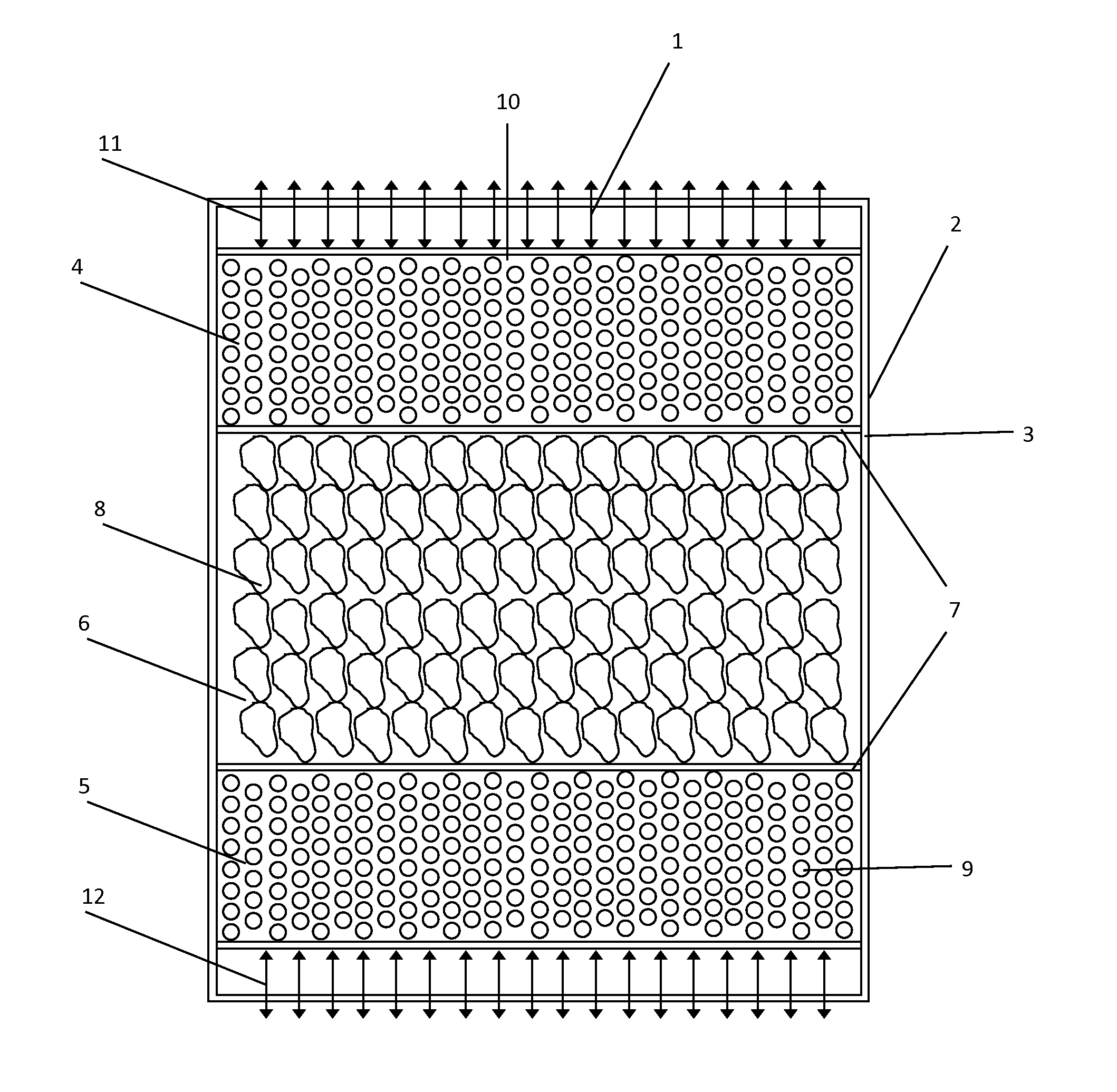
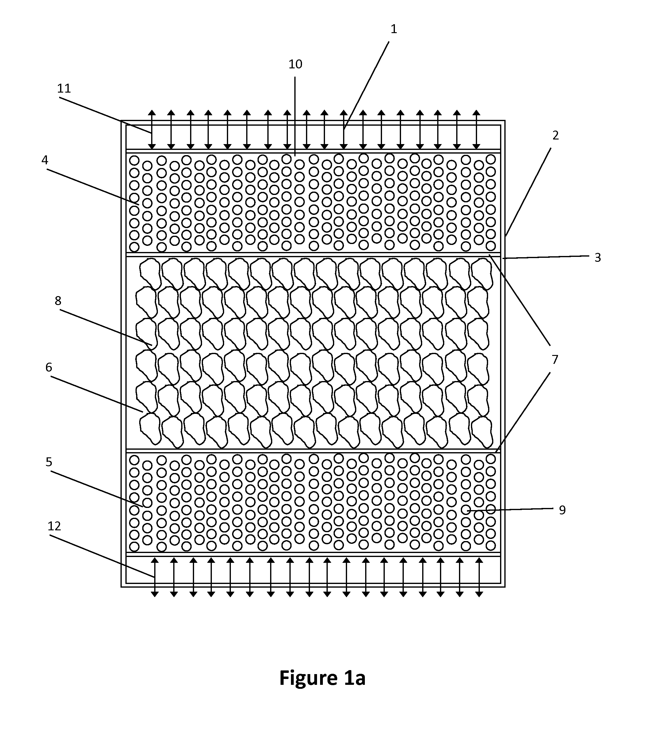
[0014]A thermocline storage tank of thermal energy is based on the principle that a hot or hotter fluid tends to position above the layers of cold temperature or with less temperature in the same cavity. This device makes use of the phenomenon of thermal stratification of a fluid, which is a consequence of the difference in densities of the fluid depending on the temperature. Different aspects such as: the turbulence generated at the entrance or at the exit of fluid from the tank, or the convection-diffusion between the layers of the fluid, the presence of thermal bridges, can affect the stratification of the fluid, fact that reduces the efficiency of the thermal storage system described herein.
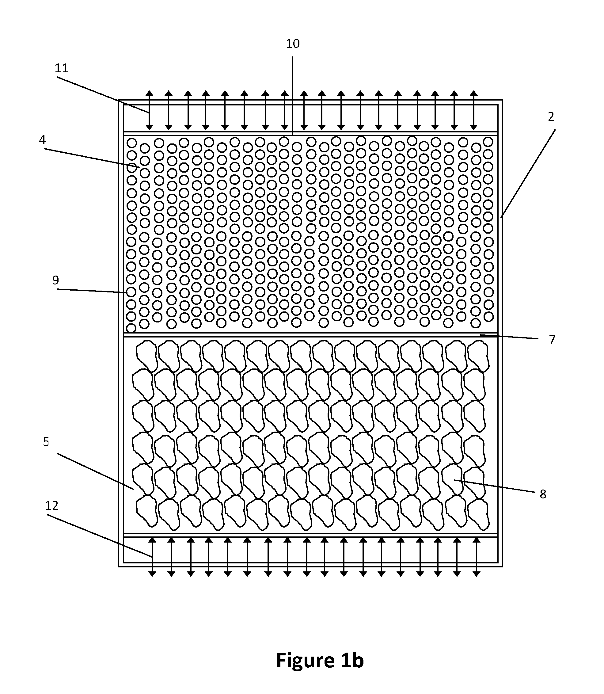
[0015]The present invention, in principle, attempts to make use of the trend effect to the positioning of the hot and the cold layers of the fluid towards the high and low zones, respectively. In effect, the entrance/exit of hot fluid as the PCM of higher melting temperature, should be located on the top part of the tank (if the tank is arranged vertically, FIGS. 1a, 1b and 1c); while the inlet outlet of the cold fluid and the PCM lower melting point, should be located at the bottom zone. However, in specific applications where such a configuration is not possible, and considering that probably most part of the energy will be stored in the mater...

Problems solved by technology

The mechanisms for obtaining thermal energy have the limitation that ually they are not continuous processes.
These processes o...

Method used


Image

  • Thermal energy storage system combining sensible heat solid material and phase change material
  • Thermal energy storage system combining sensible heat solid material and phase change material
  • Thermal energy storage system combining sensible heat solid material and phase change material

Examples


case b

[0069]Four different situations about the illustrative example described above, named case A, B, C1 and C2, are studied. Cases A and B are taken as the standard reference, whereas the cases C1 and C2 incorporate own criteria of this invention.[0070]Case A: tank completely full of sensible heat solid material (not PCM).[0071] Tank completely full of PCM of reference. Its melting temperature is set at the 60% range of operating temperatures; i.e.

[0072]Said temperature is not within the admissible outflow temperature ranges of neither of both processes[0073]C1 Case: Hybrid tank type, using two PCM, with a 20% of the height covered by PCM1, 60% by sensible heat solid material and the remaining 20% by PCM2. The melting points of the two PCM are:

[0074]The phase change temperatures of both PCM are within the admissible range of temperatures of the corresponding processes:[0075]Case C2: Hybrid tank type, using four PCM, with a 15% of PCM1, a 15% of PCM3, a 40% of sensible heat solid materia...


PUM


Abstract

The invention relates to a system for the storage and recovery of thermal energy, using, as its medium, at least one phase change material (solid-liquid) and a sensible heat solid material for storing/recovering the heat obtained from an external source in the form of phase change latent heat and sensible heat. The aforementioned materials are duly housed inside a single tank containing at least two zones which are differentiated by the range of temperatures to which they are subjected, each zone containing a different material. The most common configuration consists of three different zones located inside the tank, namely: a hot zone in the upper part of the tank, enclosing an encapsulated phase change material characterised by a high melting temperature; a cold zone housed in the lower part of the tank, containing a phase change material with a low melting temperature; and a middle zone containing a sensible heat solid material.

Description

OBJECT OF THE INVENTION[0001]The present invention describes a system of storage and recovery of thermal energy making use of the ability of the solid material to contain thermal energy in the form of sensible heat and of the capacity of the phase change material to contain thermal energy both in the form of sensible heat and of latent phase change. The invention described herein uses the heat from an external source or the waste heat from a process, charging a device (tank) of heat energy during a period of time stablished and discharging the device (tank) at a later time when the energy source is not available (or is not enough) continuously supplying thermal energy to an external system. One of the purposes of the invention is to minimize the size of the storage tank without jeopardizing the effectiveness of the same.STATE-OF-THE-ART[0002]The use of the thermal energy from an external source (e.g. solar energy, the residual heat of a manufacturing process, etc.) for generating el...

Claims


Application Information

Patent Timeline
IPC IPC(8): F28D20/02F28F21/04F28D20/00
CPCF28D20/026F28D20/0056F28D2020/0086F28F21/04F28D2020/0065F28D20/023F28D2020/006Y02E60/14
Inventor OLIVA LLENA, ASENSIPEREZ SEGARRA, CARLOS DAVIDRIGOLA SERRANO, JOAQUIMCASTRO GONZ LEZ, JES SOLIET CASASAYAS, CARLESRODR GUEZ PEREZ, IVETTELEHMKUHL BARBA, ORIOLTRIAS MIQUEL, XAVICAPDEVILA PARAMIO, ROSERALBA QUEIPO, RAMIROORDONO MART NEZ, MANUEL MIGUELGALIONE KLOT, PEDRO ANDRES
Owner UNIV POLITECNICA DE CATALUNYA
Why Eureka
Try Eureka