Boring and milling head

A boring and milling, tapered head technology, applied in the field of boring and milling heads, can solve the problems of high cost, complex processing, limited rotation angle, etc., and achieve the effect of convenient processing and manufacturing, large contact area and good neutrality

Inactive Publication Date: 2012-09-26
JIANGYIN DADI EQUIP
View PDF6 Cites 0 Cited by
  • Summary
  • Abstract
  • Description
  • Claims
  • Application Information

AI Technical Summary

Problems solved by technology

[0002] The traditional boring and milling head includes a driving device, a rotary body and a rotary joint. The rotary body is arranged between the driving device and the rotary joint. The rotary body and the rotary joint are connected through a set of Hirth discs. Figure 4 As shown, the mouse tooth plate includes an upper tooth plate 18 and a lower tooth plate 19. During operation, the ruler on the upper tooth plate 18 meshes with the teeth on the lower tooth plate 19. During continuous rotation, wear will occur between the teeth , Breakage will occur after a long time. Generally, this kind of tooth plate is made of alloy steel, the cost is relatively high, and the precision between the teeth is high, the processing is more complicated, and in the process of rotation , will be affected by the tooth spacing between each tooth, the minimum angle of each adjustment must be the angle of one tooth, so the rotation angle is limited, resulting in poor alignment

Method used


Image

  • Boring and milling head
  • Boring and milling head
  • Boring and milling head

Examples


Embodiment Construction

[0016] All features disclosed in this specification, or steps in all methods or processes disclosed, may be combined in any manner, except for mutually exclusive features and / or steps.

[0017] Any feature disclosed in this specification (including any appended claims, abstract and drawings), unless expressly stated otherwise, may be replaced by alternative features which are equivalent or serve a similar purpose. That is, unless expressly stated otherwise, each feature is one example only of a series of equivalent or similar features.

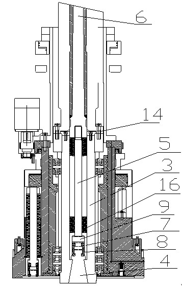
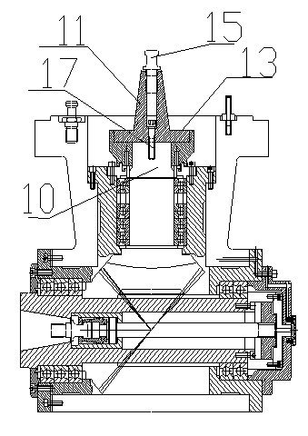
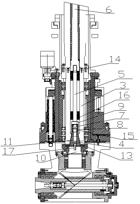
[0018] Such as figure 1 The shown boring and milling head includes a driving device and a rotary joint. A locking device is provided between the driving device 1 and the rotating joint. The driving device and the locking device are connected by a second bolt 17. The locking device includes a lock Tightening cylinder 3, the middle part of locking cylinder 3 is provided with the first cylindrical through hole, and the lower end of locking cyli...


PUM


Abstract

The invention discloses a boring and milling head, comprising a driving device and a rotary joint, wherein a locking device is arranged between the driving device and the rotary joint; the locking device comprises a locking cylinder (3); a first cylindrical through hole is formed at the middle part of the locking cylinder (3); a conical hole (4) is formed at the lower end of the locking cylinder (3); the conical hole (4) is communicated with the first cylindrical through hole; a pull rod (5) is arranged in the first cylindrical through hole; the upper end of the pull rod (5) is connected with the driving shaft (6) of the driving device; a sleeve shaft (7) is arranged at the lower end of the pull rod (5); a handle (8) and a blocking block (9) are arranged in the sleeve shaft (7); the handle (8) and the blocking block (9) are arranged on the pull rod (5); the rotary joint comprises a spindle (10); and a conical head (11) matched with the conical hole is arranged on the spindle (10). The boring and milling head provided by the invention has the advantages of large contact area, good centering property, no rotating angle limitation and low cost, and the conical head is convenient to machine and manufacture.

Description

technical field [0001] The invention relates to an accessory device of a numerically controlled gantry machine tool, in particular to a boring and milling head. Background technique [0002] The traditional boring and milling head includes a driving device, a rotary body and a rotary joint. The rotary body is arranged between the driving device and the rotary joint. The rotary body and the rotary joint are connected through a set of Hirth discs. Figure 4 As shown, the mouse tooth plate includes an upper tooth plate 18 and a lower tooth plate 19. During operation, the ruler on the upper tooth plate 18 meshes with the teeth on the lower tooth plate 19. During continuous rotation, wear will occur between the teeth , Breakage will occur after a long time. Generally, this kind of tooth plate is made of alloy steel, the cost is relatively high, and the precision between the teeth is high, the processing is more complicated, and in the process of rotation , will be affected by the...

Claims


Application Information

Patent Timeline
Patent Type & Authority Applications(China)
IPC IPC(8): B23Q5/02B23Q3/12B23P23/02
Inventor 唐瑞刚潘德杰钱坚强钱春龙
Owner JIANGYIN DADI EQUIP
Why Eureka
Try Eureka