
Method for bonding backlight module with LED (liquid crystal display) panel

A backlight module and panel technology, applied to chemical instruments and methods, layered products, lamination devices, etc., can solve problems such as hard to see, poor production, etc., to avoid dirt, improve production yield, and simple and convenient operation Effect

Active Publication Date: 2012-09-26
广东金龙机电有限公司
View PDF5 Cites 2 Cited by
  • Summary
  • Abstract
  • Description
  • Claims
  • Application Information

AI Technical Summary

Problems solved by technology

[0003] The existing technology mainly adopts manual processing. The specific process is to place the backlight module on the workbench, then put the backlight module corresponding to the LCD panel on the backlight module, and press down the LCD panel to make the LCD panel and the backlight module Assembling to form a bond, however, if there is dirt between the backlight module and the LCD panel in this bonding method, it will not be easy to see, which may lead to poor production

Method used


Image

  • Method for bonding backlight module with LED (liquid crystal display) panel
  • Method for bonding backlight module with LED (liquid crystal display) panel
  • Method for bonding backlight module with LED (liquid crystal display) panel

Examples


Embodiment Construction

[0029] In order to further illustrate the technical means adopted by the present invention and its effects, a detailed description is given below in conjunction with the preferred embodiments of the present invention and the accompanying drawings.

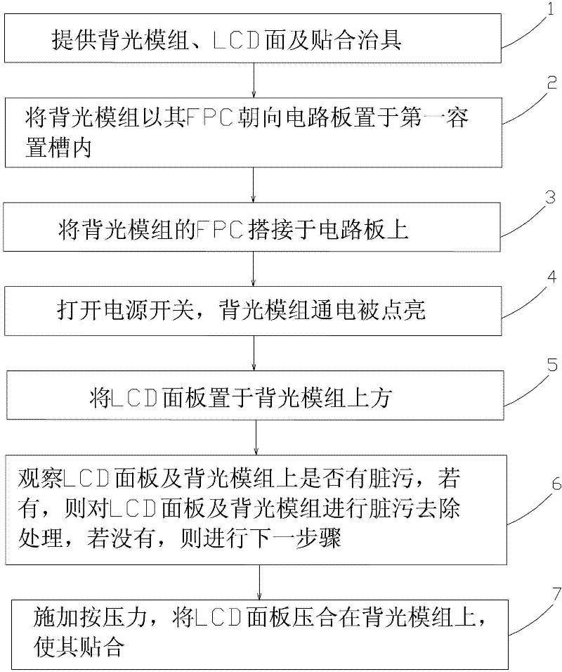
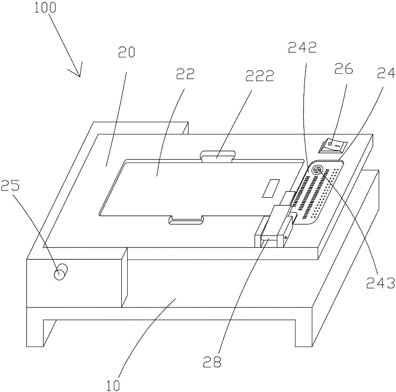
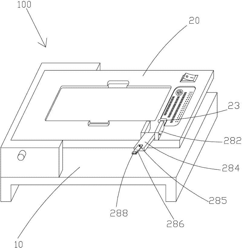
[0030] see figure 1 As shown, it is a flow chart of the bonding method of the backlight module of the present invention and the LCD panel, combined with Figure 2-3 As shown, the bonding method of the backlight module of the present invention and the LCD panel comprises the following steps:

[0031] Step 1. Provide a backlight module (not shown), an LCD panel (not shown) and a bonding jig 100, and the backlight module and the LCD panel are arranged correspondingly. The laminating jig 100 includes a base 10 and a supporting platform 20 which can be opened and closed on the base 10 . The supporting platform 20 is provided with a first accommodating groove 22 , a circuit board 242 and a power switch 26 . The circuit board 242 is loc...


PUM


Abstract

The invention provides a method for bonding a backlight module with an LED (liquid crystal display) panel; the method comprises the step 1 of providing a backlight module, an LED (liquid crystal display) panel and a bonding fixture; the step 2 of arranging the backlight module into a first containing slot in a way that a FPC (flexible printed circuit) of the backlight module faces a circuit board; the step 3 of jointing the FPC (flexible printed circuit) of the backlight module on the circuit board; the step 4 of turning on a power switch in order to lighten the electrified backlight module; the step 5 of arranging the LED (liquid crystal display) panel on the backlight module; the step 6 of observing whether the LED (liquid crystal display) panel and the backlight module are polluted by a sludge, if yes, cleaning the LED (liquid crystal display) panel and the backlight module, and otherwise, performing the next step; and the step 7 of compressing the LED (liquid crystal display) panel on the backlight module in order to bond both the LED panel and the backlight module. The method for bonding the backlight module with the LED (liquid crystal display) panel is simple and convenient in operation, in this way, the bonding quality of the backlight module and the LED (liquid crystal display) panel is guaranteed and the production yield is improved.

Description

technical field [0001] The invention relates to the field of LCD (Liquid Crystal Display) production, in particular to a method for laminating a backlight module and an LCD panel. Background technique [0002] Liquid Crystal Display (LCD, Liquid Crystal Display) has many advantages such as thin body, power saving, no radiation, etc., and has been widely used. Most of the liquid crystal display devices on the market are backlight type liquid crystal displays, which include a liquid crystal display panel and a backlight module. The working principle of the liquid crystal display panel is to place liquid crystal molecules in two parallel pieces of glass. There are many vertical and horizontal small wires between the two pieces of glass. The direction of the liquid crystal molecules is controlled by whether the power is turned on or not, and the light of the backlight module is refracted. generate screen. Since the liquid crystal display panel itself does not emit light, it ne...

Claims


Application Information

Patent Timeline
Patent Type & Authority Applications(China)
IPC IPC(8): B32B37/10
Inventor 乔伟雄
Owner 广东金龙机电有限公司
Learn More