Pipeline welding process

A welding process and pipeline technology, used in welding equipment, auxiliary welding equipment, welding/cutting auxiliary equipment, etc., can solve the problems of centrifugal force generated by the pipeline, affecting the tight quality of the pipeline, and cumbersome rotation of long pipelines, so as to ensure the welding quality. Effect

Pending Publication Date: 2022-04-22
李明泽
View PDF0 Cites 0 Cited by
  • Summary
  • Abstract
  • Description
  • Claims
  • Application Information

AI Technical Summary

Problems solved by technology

[0004] In order to make up for the deficiencies of the existing technology, the solution is to rotate the pipes to facilitate the welding process when the pipes are fully welded. However, when some longer pipes are welded, the rotation of the long pipes is more cumbersome and inconvenient. Moreover, the rotation of the pipeline will generate centrifugal force, which will affect the quality of the tight fit between the two pipelines, and then affect the welding quality. A welding process for pipelines proposed by the present invention

Method used


Image

  • Pipeline welding process
  • Pipeline welding process
  • Pipeline welding process

Examples


Embodiment 1

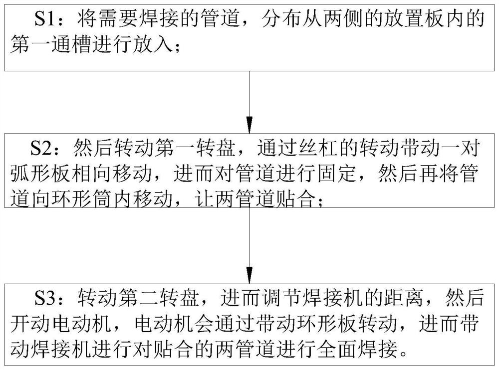
[0032] Such as Figure 1 to Figure 6 Shown, the welding process of a kind of pipeline of the present invention, this process step is as follows:

[0033] S1: Distribute the pipes to be welded into the first through grooves 11 in the placement plates 1 on both sides;

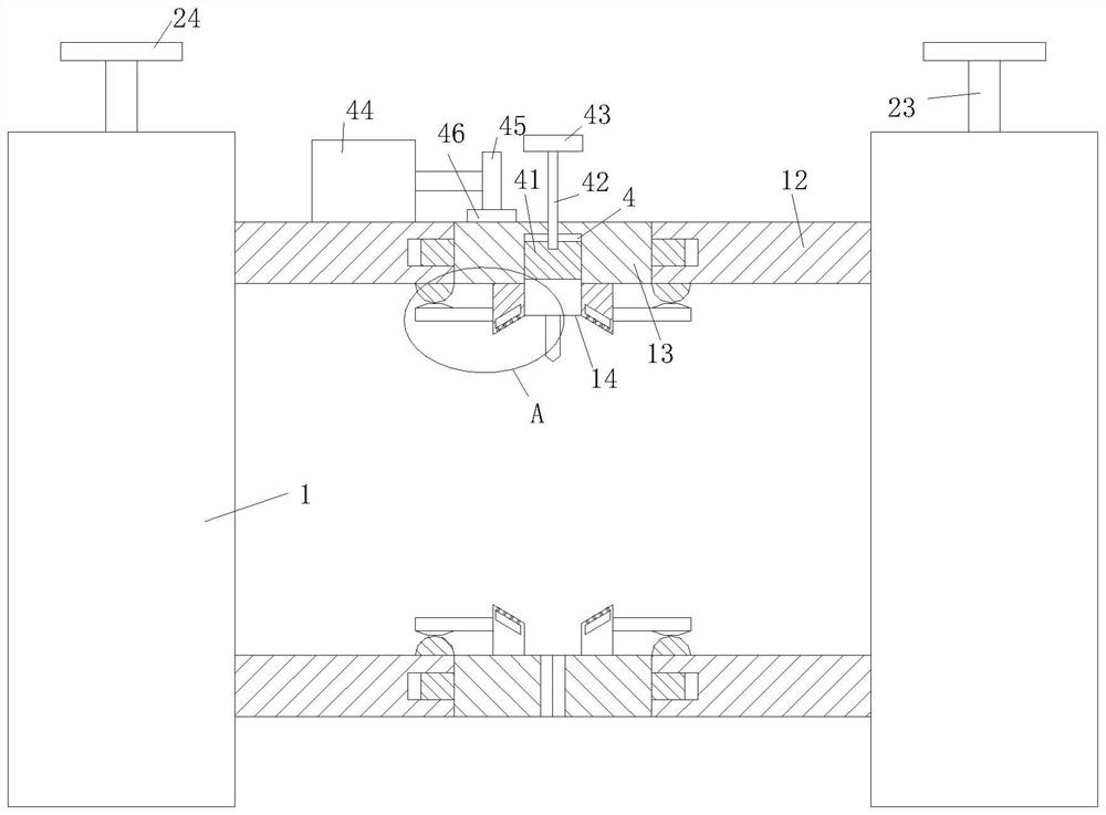
[0034] S2: Then turn the first turntable 24, the rotation of the lead screw 23 drives the pair of arc-shaped plates 22 to move toward each other, and then fix the pipeline, and then move the pipeline into the annular cylinder 12, so that the two pipelines fit together;

[0035] S3: Rotate the second turntable 43 to further adjust the distance of the welding machine 14, and then start the motor 44. The motor 44 will drive the ring plate 13 to rotate, and then drive the welding machine 14 to fully weld the two attached pipes.

[0036]It includes a placement plate 1; a pair of said placement plates 1 side walls are provided with a first through groove 11; a pair of said placement plates 1 is fixed with an annular c...

Embodiment 2

[0045] Such as Figure 7 As shown in Comparative Example 1, as another embodiment of the present invention, a layer of anti-skid pad 58 is fixedly attached to the outer wall of the roller 32; the anti-skid pad 58 is made of rubber; An anti-slip pad 58 is provided on the top, which can avoid the horizontal and axial sliding of the pipeline on the roller 32, can ensure the stability of the fixed welding, and then ensure the welding effect of the two pipelines.

[0046] Working principle: When the long pipe needs to be welded, the two pipes can be distributed, and the welding end can be extended into the annular cylinder 12 through the first through groove 11, and then the long pipe can be welded through the clamping piece in the first through groove 11. fixed, then by rotating the annular plate 13, and then through the welding machine 14 to fully process the fitted pipe wall, through the rotation of the welding machine 14, the influence of centrifugal force on the pipe fitting c...


PUM


Abstract

The invention belongs to the technical field of pipeline welding, and particularly relates to a pipeline welding process. The invention provides a pipeline welding process which comprises the following steps: S1, pipelines to be welded are put in from first through grooves in placement plates on two sides; s2, then a first rotating disc is rotated, a pair of arc-shaped plates are driven to move oppositely through rotation of a lead screw, then the pipelines are fixed, then the pipelines are moved into an annular cylinder, and the two pipelines are attached; s3, a second rotating disc is rotated, then the distance of a welding machine is adjusted, then a motor is started, the motor drives an annular plate to rotate, and then the welding machine is driven to conduct comprehensive welding on the two attached pipelines; the problems that centrifugal force can be generated by rotation of the pipelines, the attaching tight quality between the two pipelines can be affected, and then the welding quality is affected are solved.

Description

technical field [0001] The invention belongs to the technical field of pipeline welding, in particular to a pipeline welding process. Background technique [0002] At present, pipelines are needed in urban construction, and metal pipelines are used in a wider range. Metal pipelines can be used to transport fluids such as gas and liquid. Therefore, different pipelines need to be welded in daily use to meet the different needs of users. [0003] In the prior art, when the pipeline is fully welded, the pipeline is rotated to facilitate the welding process. However, when some long pipelines are welded, the rotation of the long pipeline is cumbersome and inconvenient, and the rotation of the pipeline Centrifugal force will be generated, which will affect the close quality of the two pipes, and further affect the welding quality. Therefore, the present invention provides a welding process for pipes. Contents of the invention [0004] In order to make up for the deficiencies of ...

Claims


Application Information

Patent Timeline
IPC IPC(8): B23K37/053B23K37/04B23K37/00B23K101/06
CPCB23K37/0533B23K37/0426B23K37/003B23K2101/06
Inventor 李明泽
Owner 李明泽
Why Eureka
Try Eureka