Hydraulic control valve device

A hydraulic control valve, control valve technology, applied in fluid pressure actuators, servo motors, servo meter circuits, etc., can solve the problems of high coordination, low efficiency, wide bandwidth, etc., achieve stable adjustment characteristics, avoid vibration problems, The effect of improving efficiency

Active Publication Date: 2012-09-26
LINDE HYDRAULICS
View PDF7 Cites 5 Cited by
  • Summary
  • Abstract
  • Description
  • Claims
  • Application Information

AI Technical Summary

Problems solved by technology

[0005] However, in the known control valve arrangement in which the check valve arranged on the discharge side is controlled by the pressure prevailing on the inflow side leads to vibration problems which sometimes make it impossible to suppress the Loads acting on hydraulic cylinders, e.g. traction loads
In order to suppress these vibrations, a high coordination effort is required between the load holding valve and its actuation by means of the throttling device
However, due to the large bandwidth of the load drop, a stable state cannot be achieved forever, but usually only a compromise solution can be achieved
In addition, the connection of the inflow side of the hydraulic cylinder to the tank via the pilot line of the anti-drop valve and the throttle arranged therein leads to a power loss, which leads to a reduction in efficiency

Method used


Image

  • Hydraulic control valve device
  • Hydraulic control valve device

Examples


Embodiment Construction

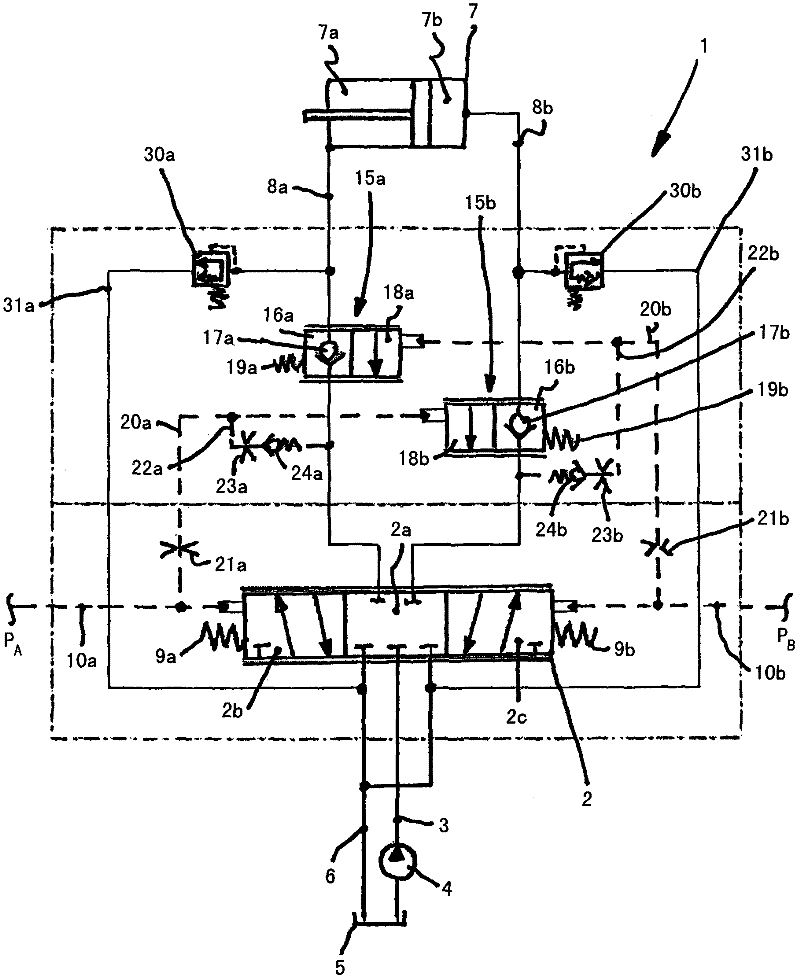
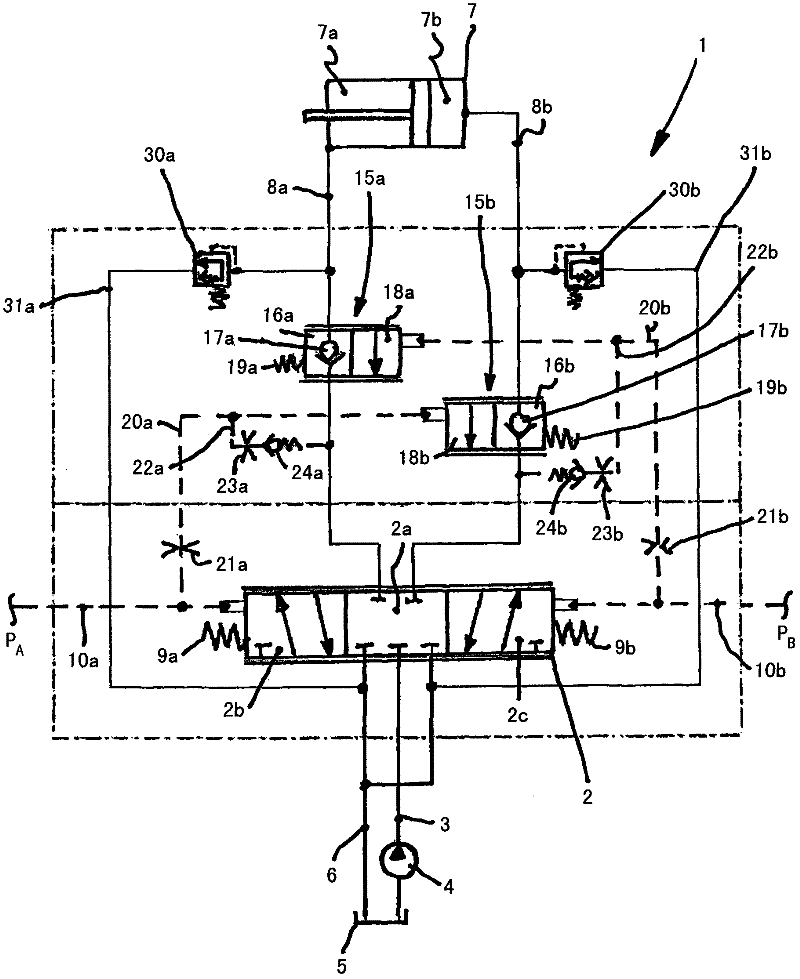
[0013] The control valve arrangement 1 comprises a control valve 2 configured as a directional control valve throttled in an intermediate position, which is connected to the delivery line 3 of a pump 4 operated in an open circuit and to a container 5 On the container pipeline 6.

[0014] The control valve 2 controls the direction of movement and the speed of movement of the double-acting hydraulic cylinder 7, wherein the control valve 2 is connected to the first pressure chamber 7a of the hydraulic cylinder 7 by means of a first consumer line 8a and by means of The second consumer line 8b is connected to the second pressure chamber 7b of the hydraulic cylinder 7 .

[0015] The control valve 2 has a blocking position 2 a configured as a neutral position, in which the connection of the consumer lines 8 a , 8 b to the delivery line 3 and the container line 6 is blocked. In the first control position 2 b of the control valve 2 , the first consumer line 8 a is connected to the del...


PUM


Abstract

The hydraulic control valve device (1) has a throttling control valve (2), which is arranged in an intermediate position with a conveying line (3) and a pump (4), where an outlet side fitting tight counter-balance valve (15a) is arranged in the direction of a flow position (18a) for being operated with a control pressure (pA) of the control valve. Multiple throttle units (21a,21b,23a,23b) are formed as diaphragms or nozzles.

Description

technical field [0001] The invention relates to a hydraulic control valve arrangement for controlling a double-acting hydraulic cylinder, which has a control valve throttled in an intermediate position, which control valve is connected to the delivery line of the pump, the container line to the container and Consumer line connections to the hydraulic cylinders, wherein the control valves are each actuated by hydraulic control pressure in the direction of a control position in which a consumer line forms a connection to the delivery line On the inflow side and a second consumer line is formed in the discharge line connected to the container, wherein a matching sealing stop for shutting off the hydraulic cylinder without oil leakage is arranged in each of these consumer lines A drop valve having a leak-tight shut-off position and a flow-through position. Background technique [0002] A control valve arrangement of this type is known from DE 102 24 731 A1 for controlling a til...

Claims


Application Information

Patent Timeline
Patent Type & Authority Applications(China)
IPC IPC(8): F15B11/04
CPCF15B2211/50527F15B2211/7053F15B2211/30515F15B11/003
Inventor W・卡拉夫特
Owner LINDE HYDRAULICS
Why Eureka
Try Eureka