Load controllable active type follow-up force-applying linear guide rail pair test bed

A linear guide pair, active technology, applied in the testing of mechanical components, testing of machine/structural components, measuring devices, etc., can solve problems such as difficult quantitative prediction, unstable and complex changes in the load of four guide rail sliders

Inactive Publication Date: 2014-08-06
SOUTHWEST JIAOTONG UNIV
View PDF5 Cites 0 Cited by
  • Summary
  • Abstract
  • Description
  • Claims
  • Application Information

AI Technical Summary

Problems solved by technology

However, since the force application points of the lateral loading mechanism and the vertical loading mechanism are fixed, they do not move with the movement of the stressed slide table; while the force slide table is always in a moving state during the test, the fixed force application point and the four guide rail sliders The relative distance of the force slide table changes, so the load distributed to the four guide rail sliders by the force slide table is not constant, but affected by the relative distance and the slide speed of the force slide table, the change is complex and difficult to predict quantitatively
That is to say, the loads applied to the four rail sliders by the lateral loading mechanism and the vertical loading mechanism are inconvenient and accurate to control
Therefore, the test device cannot accurately and reliably evaluate the relationship between the load and the performance and life of the guide rail pair

Method used


Image

  • Load controllable active type follow-up force-applying linear guide rail pair test bed
  • Load controllable active type follow-up force-applying linear guide rail pair test bed

Examples


Embodiment approach

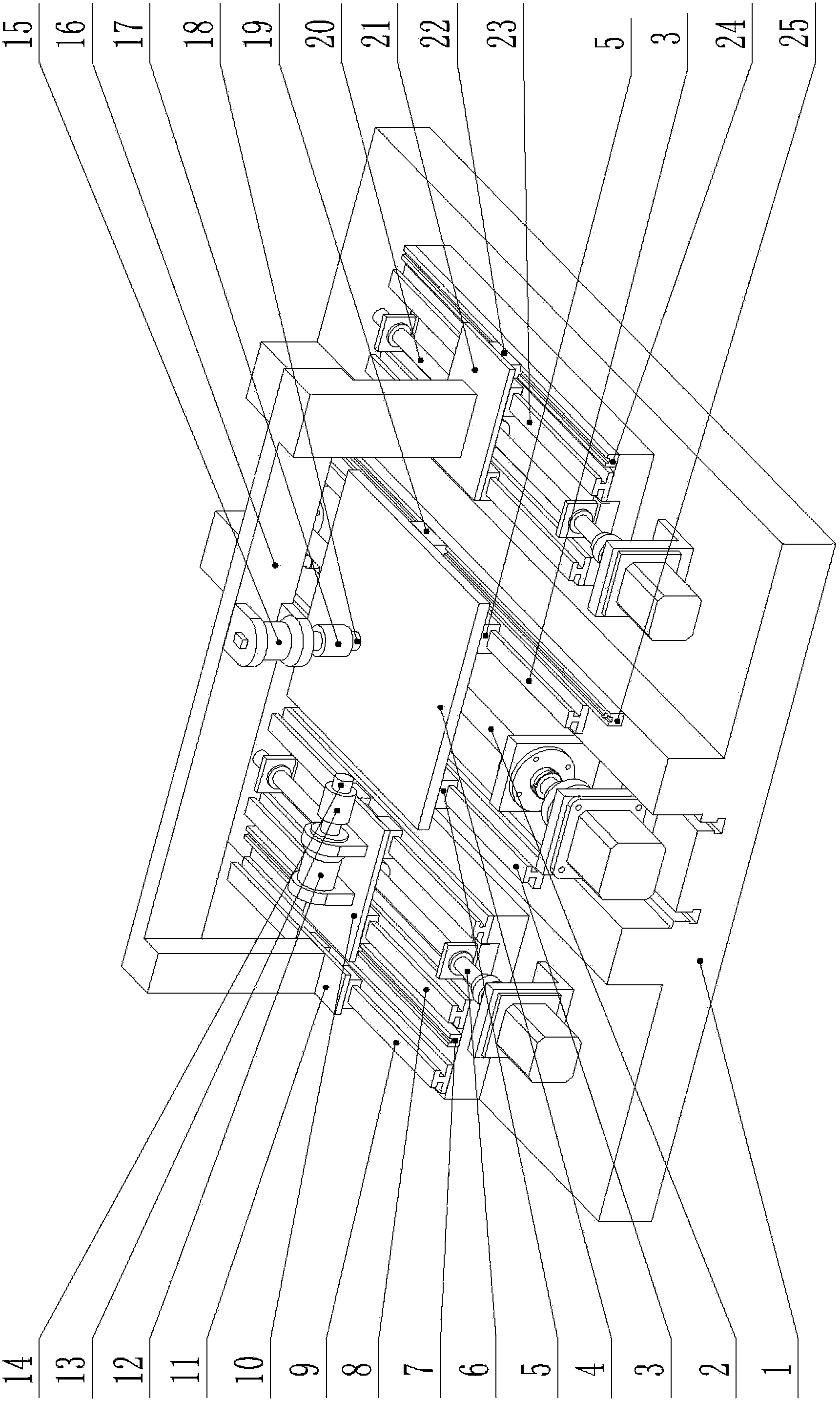
[0029] figure 1It is shown that the first specific embodiment of the present invention is a load-controllable active follow-up force-applying linear guide rail auxiliary test bench, which consists of:

[0030] The machine base 1, the screw drive mechanism 2 on the machine base 1, and the two guide rails 3 are respectively installed on both sides of the screw drive mechanism 2, and the bottom surface of the stressed slide table 4 is connected with the lead screw drive mechanism 2, and the stressed slide table 4 The four corners of the bottom surface are correspondingly connected with the four guide rail sliders 5, and each two of the four guide rail sliders 5 form a guide rail pair with the corresponding guide rail 3; the lower surface of the stressed slide table 4 is also connected with a grating ruler reading head 19. The grating ruler reading head 19 cooperates with the grating ruler main ruler 25 fixed on the machine base 1. The side of the stressed slide table 4 has a late...

Embodiment 2

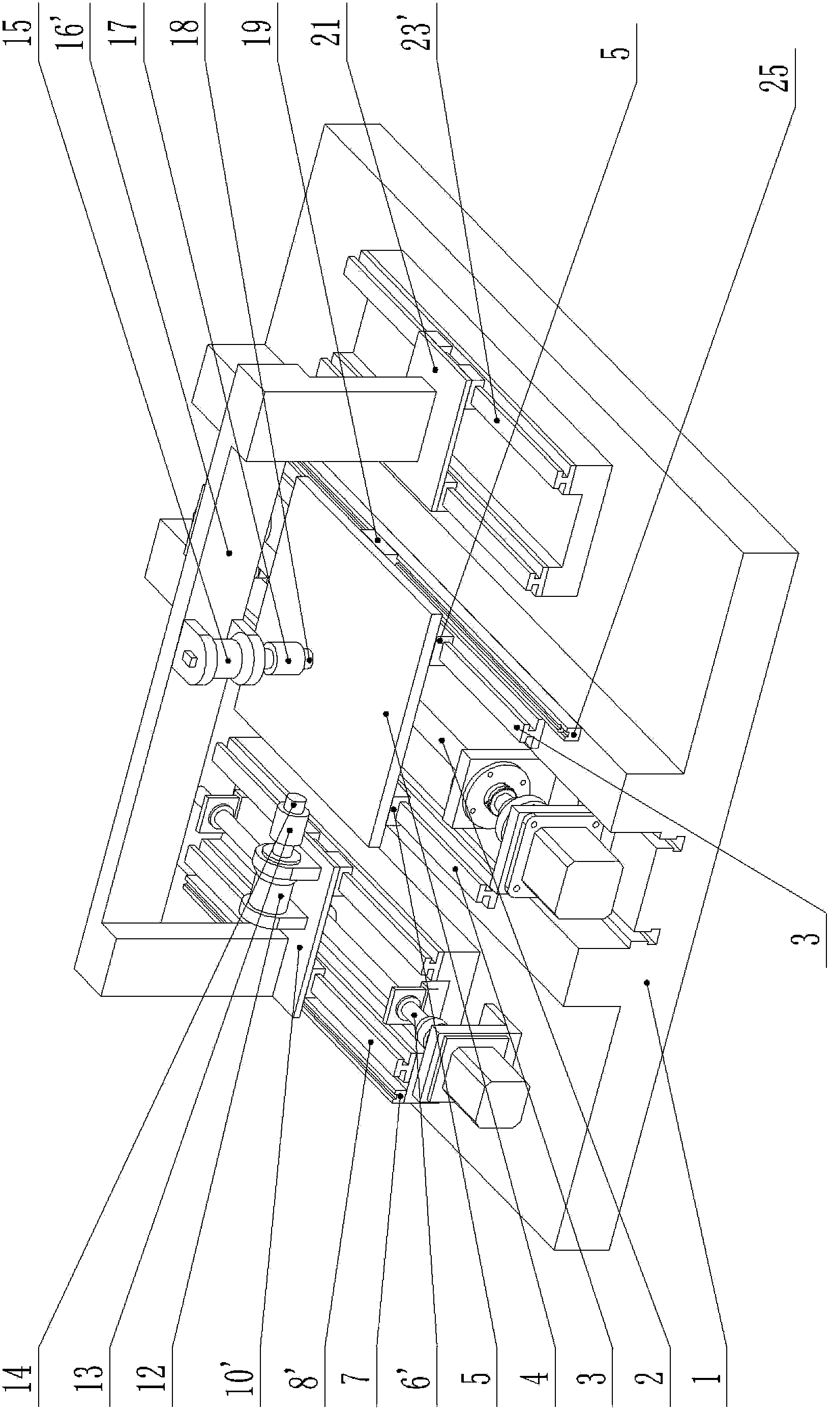
[0035] figure 2 It is shown that the second specific embodiment of the present invention is a load-controllable active follow-up force-applying linear guide rail auxiliary test bench, which consists of:

[0036] The machine base 1, the screw drive mechanism 2 on the machine base 1, and the two guide rails 3 are respectively installed on both sides of the screw drive mechanism 2, and the bottom surface of the stressed slide table 4 is connected with the lead screw drive mechanism 2, and the stressed slide table 4 The four corners of the bottom surface are correspondingly connected with the four guide rail sliders 5, and each two of the four guide rail sliders 5 form a guide rail pair with the corresponding guide rail 3; the lower surface of the stressed slide table 4 is also connected with a grating ruler reading head 19. The grating ruler reading head 19 cooperates with the grating main ruler 25 fixed on the machine base 1, and the side of the stressed slide table 4 has a lat...


PUM


Abstract

The invention relates to a load controllable active type follow-up force-applying linear guide rail pair test bed. Force-applying heads (force-applying points) of a transverse loading mechanism and a vertical loading mechanism independently use or share a lead screw driving mechanism so that the transverse loading mechanism and the vertical loading mechanism move synchronously along with a stressed sliding table and the force-applying points are relatively stationary with four guide rail sliding blocks. Therefore, loads applied by a force-applying device can be uniformly and invariably acted on the four guide rail sliding blocks. The load born by each guide rail sliding block is 1 / 4 of that applied by the fore-applying device, namely, change curves of the loads born by the guide rail sliding blocks are completely consistent with the change curves of force applied by the force-applying device, only the amplitude is reduced to 1 / 4. Therefore, when the load controllable active type follow-up force-applying linear guide rail pair test bed is used for carrying out a performance and service life test on the linear guide rail pair, the load applied can be conveniently, precisely and reliably controlled so as to relatively accurately and reliably evaluate a relationship among the load, the performance and service life of the linear guide rail pair, thus providing a relatively reliable test basis for design and maintenance of the guide rail pair.

Description

technical field [0001] The invention relates to a load-controllable active follow-up force-applying linear guide rail auxiliary test bench. Background technique [0002] Linear guide rail pair is a common guiding part of mechanical system, and it is widely used in various machinery and equipment. Its performance and life are mainly related to the lateral load and radial (perpendicular to the front of the guide rail) load of the guide rail slider. The performance and life of the guide rail pair can be evaluated by simulating the operating state of the guide rail pair under a specific load by the linear guide pair test device, which is conducive to establishing a reasonable and effective maintenance plan and saving a lot of maintenance costs. The existing linear guide rail pair test device, such as the patent application No. 201110321929.0 that the applicant has applied for "a reconfigurable lead screw pair, guide rail pair accelerated life electro-hydraulic servo test bench"...

Claims


Application Information

Patent Timeline
Patent Type & Authority Patents(China)
IPC IPC(8): G01M13/00
Inventor 高宏力张筱辰黄海凤许明恒郭亮文娟陈晨
Owner SOUTHWEST JIAOTONG UNIV
Why Eureka
Try Eureka