Displacement control mode of rotor of direct-drive switched-reluctance planar motor

A switched reluctance, planar motor technology, applied in the direction of electric components, electrical components, electromechanical devices, etc., can solve the problems that cannot meet the high precision, high speed, small electromagnetic thrust of the mover and large fluctuation of the direct drive switched reluctance planar motor. And other issues

Inactive Publication Date: 2013-11-20
TAIYUAN UNIV OF TECH
View PDF5 Cites 0 Cited by
  • Summary
  • Abstract
  • Description
  • Claims
  • Application Information

AI Technical Summary

Problems solved by technology

At present, the direct-drive switched reluctance planar motor adopts the control method of single-phase mover winding energization, which has the problems of small electromagnetic thrust of the mover, large fluctuations, and unstable operation, which cannot meet the high precision and high-precision requirements of the direct-drive switched reluctance planar motor. high speed requirements

Method used


Image

  • Displacement control mode of rotor of direct-drive switched-reluctance planar motor
  • Displacement control mode of rotor of direct-drive switched-reluctance planar motor
  • Displacement control mode of rotor of direct-drive switched-reluctance planar motor

Examples


Embodiment approach 1

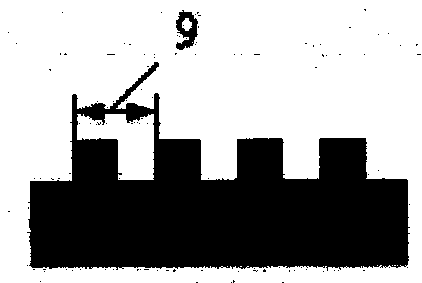
[0037] The displacement movement of the mover 7 changes periodically, and the movement cycle is equal to the stator pole distance 9, which is 12mm. Each cycle is divided into six equal parts, and the six different positions of the mover 7 relative to the stator 8 determine the position of the mover winding. power-on state.

[0038] When the mover 7 moves to the right in the x direction, the winding sequence is as follows:

[0039] I, X C The phase mover winding 1 is energized, at this time the mover teeth 12 of phase A are aligned with the stator teeth 10, and the mover 7 moves to the right by 1 / 6 of the stator pole pitch 9, which is 2mm;

[0040] II, X C Phase mover winding 1 and X B The phase mover winding 2 is energized at the same time, at this time, the B phase mover teeth 13 are aligned with the stator slot 11, and the mover 7 moves to the right by 1 / 6 of the stator pole pitch 9, which is 2mm;

[0041] III, X B The phase mover winding 2 is energized, at this time th...

Embodiment approach 2

[0050] The displacement movement of the mover 7 changes periodically, and the movement cycle is equal to the stator pole distance 9, which is 18mm. Each cycle is divided into six equal parts, and the six different positions of the mover 7 relative to the stator 8 determine the position of the mover winding. power-on state.

[0051] When the mover 7 moves to the right in the x direction, the winding sequence is as follows:

[0052] I, X C The phase mover winding 1 is energized, at this time the mover teeth 12 of phase A are aligned with the stator teeth 10, and the mover 7 moves to the right by 1 / 6 of the stator pole pitch 9, which is 3mm;

[0053] II, X C Phase mover winding 1 and X B The phase mover winding 2 is energized at the same time, at this time the B phase mover teeth 13 are aligned with the stator slot 11, and the mover 7 moves to the right by 1 / 6 of the stator pole pitch 9, which is 3mm;

[0054] III, X B The phase mover winding 2 is energized, at this time the...

Embodiment approach 3

[0059] The displacement movement of the mover 7 changes periodically, and the movement cycle is equal to the stator pole distance 9, which is 24mm. Each cycle is divided into six equal parts, and the six different positions of the mover 7 relative to the stator 8 determine the position of the mover winding. power-on state.

[0060] When the mover 7 moves to the right in the x direction, the winding sequence is as follows:

[0061] I, X C The phase mover winding 1 is energized, at this time the A phase mover teeth 12 are aligned with the stator teeth 10, and the mover 7 moves to the right by 1 / 6 of the stator pole pitch 9, which is 4mm;

[0062] II, X C Phase mover winding 1 and X B The phase mover winding 2 is energized at the same time, at this time, the B phase mover teeth 13 are aligned with the stator slot 11, and the mover 7 moves to the right by 1 / 6 of the stator pole pitch 9, which is 4mm;

[0063] III, X B The phase mover winding 2 is energized, at this time the C...


PUM


Abstract

The invention disclose a displacement control mode of a rotor of a direct-drive switched-reluctance planar motor, belongs to the field of electromechanical control researches, and specifically relates to a displacement control of a rotor of a direct-drive switched-reluctance planar motor. The displacement control mode disclosed by the invention is characterized in that the displacement motion of a rotor 7 of a direct-drive switched-reluctance planar motor is changed cyclically, and the cycle of motion of the rotor 7 is equal to the pole pitch of a stator 9 and is 12-24 mm; and through dividing each cycle of motion into six equal parts, the control mode disclosed by the invention has the advantages that the power-on states of rotor windings are determined according to six different positions of the rotor 7 relative to a stator 8, because the cycle of motion of the rotor 7 is equal to the pole pitch of the stator 9, each rotor winding is equal in power-on time and displacement, so that the rotor 7 operates stably, thereby facilitating the accurate positioning of the rotor 7; and two phases of rotor windings are power-on simultaneously, so that the electromagnetic thrust of the rotor 7 is increased, and the running speed of the rotor 7 is increased.

Description

technical field [0001] The invention discloses a method for controlling the mover displacement of a direct-drive switched reluctance planar motor, which belongs to the field of electromechanical control research, and specifically relates to the mover displacement control of a direct-drive switched reluctance planar motor. Background technique [0002] The direct-drive switched reluctance planar motor is a mechatronic device that has self-starting capability in the x-direction and y-direction of the plane, and can directly drive the mover to do planar motion. It fundamentally gets rid of the "low-dimensional motion mechanism superposition The model of forming a high-dimensional motion mechanism can be used in plane welding machines, large-scale integrated circuit processing and packaging, printed circuit board production, probe monitors, plane measuring instruments, robot drives and other fields. [0003] Due to the complexity of the structure and arrangement of the stator an...

Claims


Application Information

Patent Timeline
Patent Type & Authority Patents(China)
IPC IPC(8): H02K41/00H02K41/03
Inventor 马春燕陈燕李更新王颖
Owner TAIYUAN UNIV OF TECH
Why Eureka
Try Eureka