Auxiliary pushing mechanism for die scrap discharge

A material pushing mechanism and waste material technology, which is applied in the direction of forming tools, manufacturing tools, and pushing equipment, etc., can solve the problems of waste material card slot accumulation, etc., and achieve the effect of reducing manufacturing costs, good effect, and reducing the minimum included angle

Active Publication Date: 2012-10-03
CHERY AUTOMOBILE CO LTD
View PDF5 Cites 3 Cited by
  • Summary
  • Abstract
  • Description
  • Claims
  • Application Information

AI Technical Summary

Problems solved by technology

[0003] The invention designs an auxiliary pushing mechanism for the discharge of mold waste, which solves the problem of frequent accumulation of waste stuck in grooves when the die waste of stamping parts is discharged

Method used


Image

  • Auxiliary pushing mechanism for die scrap discharge
  • Auxiliary pushing mechanism for die scrap discharge
  • Auxiliary pushing mechanism for die scrap discharge

Examples


Embodiment Construction

[0023] Attached below figure 1 to attach image 3 , the present invention is further described:

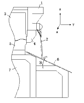
[0024] figure 1 It shows an assembly diagram of an auxiliary pushing mechanism for ejecting mold waste. The auxiliary pushing mechanism 2 is arranged on the upper mold body 1 and is located on the side where the mold produces waste, that is, the pressing core 3 and the upper mold trimming knife block 4 and the right side of lower die trimming cutter block 5, and above the waste slide plate 6, the waste slide plate 6 is at an angle with the press workbench that is arranged on the lower die body 7.

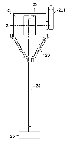
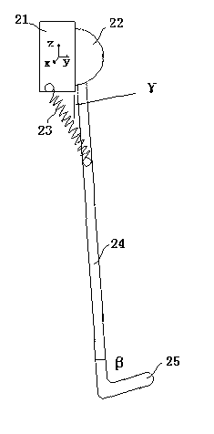
[0025] figure 2 and image 3 Shown is the schematic structural view of the auxiliary pushing mechanism, and the auxiliary pushing mechanism 2 includes a fixing device, a hinge 22, a resetting device, a connecting rod 24 and a pushing plate 25; among the present invention, the fixing device is a permanent magnet sucker 21, and the resetting device is a spring 23; the upper end of t...


PUM


Abstract

The invention relates to an auxiliary pushing mechanism for die scrap discharge. The auxiliary pushing mechanism (2) comprises a permanent magnetic chuck (21), a hinge (22), springs (23), a connecting rod (24) and a push plate (25); the permanent magnetic chuck (21) is arranged on a die main body (1), the upper end of the connecting rod (24) is hinged with the permanent magnetic chuck (21) through the hinge (22), the connecting rod (24) rotates around an X axis relative to the permanent magnetic chuck (21), and the lower end of the connecting rod (24) is provided with the push plate (25); and two springs (23) are arranged, and are symmetrically arranged around the connecting rod (24), the upper ends of the springs (23) are arranged on the permanent magnetic chuck (21), the lower ends of the springs (23) are arranged on the connecting rod (24), and the types of the springs can be selected according to the practical conditions. The auxiliary pushing mechanism has a simple structure, is low in cost, has strong universality, is convenient and flexible to apply, and easy to popularize.

Description

technical field [0001] The invention relates to an auxiliary pushing mechanism for discharging mold waste. Background technique [0002] Automobile body stamping parts mold waste is mostly discharged only by inclined waste slides. Whether the waste is discharged smoothly is limited by the degree of inclination of the waste slide, the burrs of the waste, the size and shape of the waste, and the friction between the waste and the waste slide. It is often encountered that the waste material forms a blockage when the waste slide plate slides down, causing the waste material to not slide down normally, and the accumulation of waste material slots occurs, especially on high-speed lines and multi-station production lines, which may cause production accidents. Moreover, this device requires that the included angle between the scrap slide plate and the press worktable is а≥25°. During the design process, the mold is required to have enough sliding space, which increases the difficult...

Claims


Application Information

Patent Timeline
Patent Type & Authority Applications(China)
IPC IPC(8): B21D45/04B21D37/10
Inventor 李炳炎
Owner CHERY AUTOMOBILE CO LTD
Why Eureka
Try Eureka