Feeder

A feeder and feeding mechanism technology, which is applied in the field of CNC machine tools, can solve the problems of long structure, large space occupation, and high noise of the feeder, and achieve the effects of fully automatic operation, reducing axial movement and reducing noise.

Active Publication Date: 2012-10-03
宁波宫铁智能科技有限公司
View PDF5 Cites 4 Cited by
  • Summary
  • Abstract
  • Description
  • Claims
  • Application Information

AI Technical Summary

Problems solved by technology

[0002] When processing long bars on CNC lathes, the manual feeding method was generally used in the past. There is no suitable auxiliary feeding device. The conveying position and pushing force are uneven, and the processing quality cannot reach a uniform standard. There are security risks
[0003] With the development and progress of science and technology, people began to design a feeder to assist feeding to replace the original manual feeding method. The feeder uses the driving ejector to push the long bar into the lathe processing position. There are some problems

Method used


Image

  • Feeder
  • Feeder
  • Feeder

Examples


Embodiment Construction

[0025] The following are specific embodiments of the present invention and in conjunction with the accompanying drawings, the technical solutions of the present invention are further described, but the present invention is not limited to these embodiments.

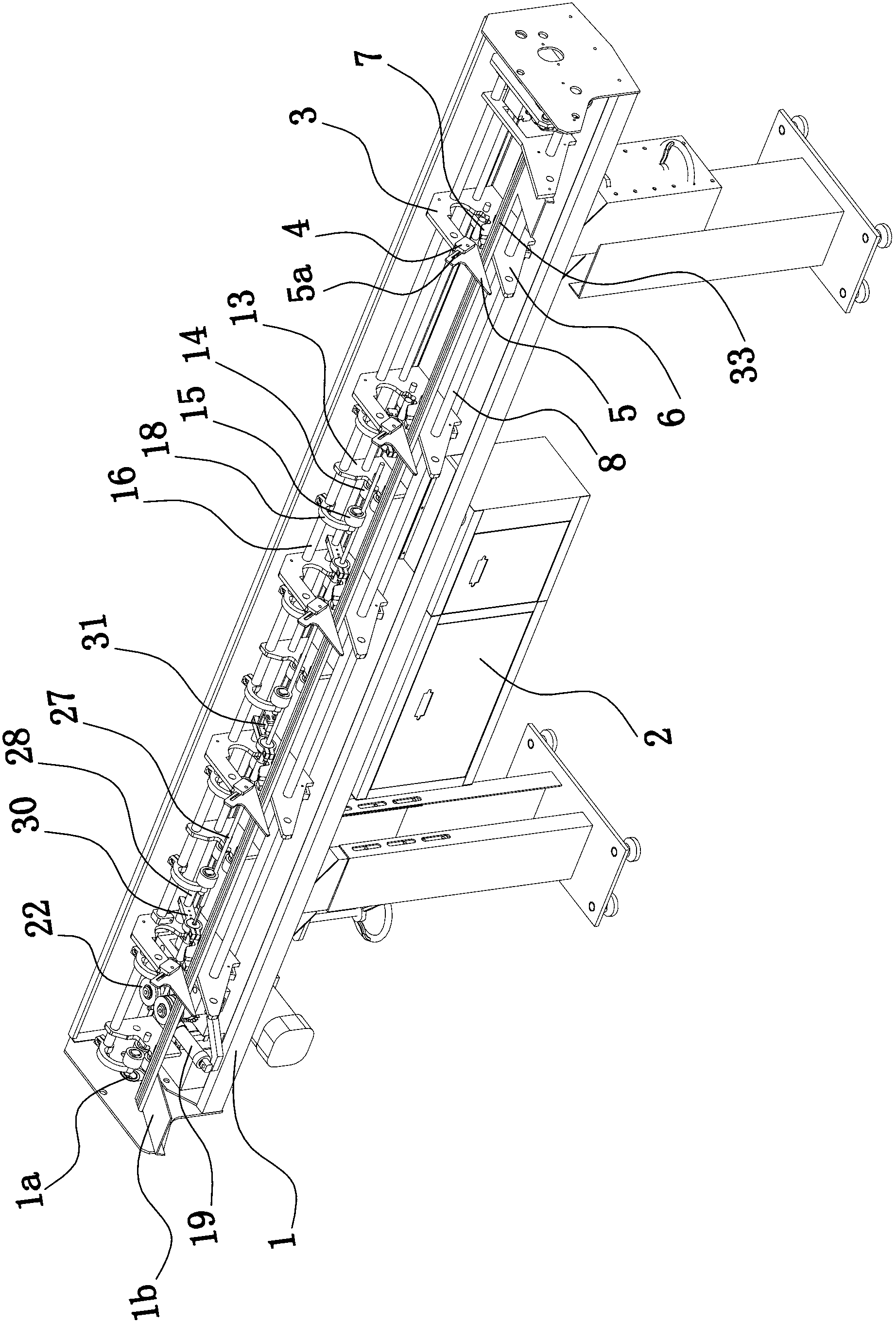
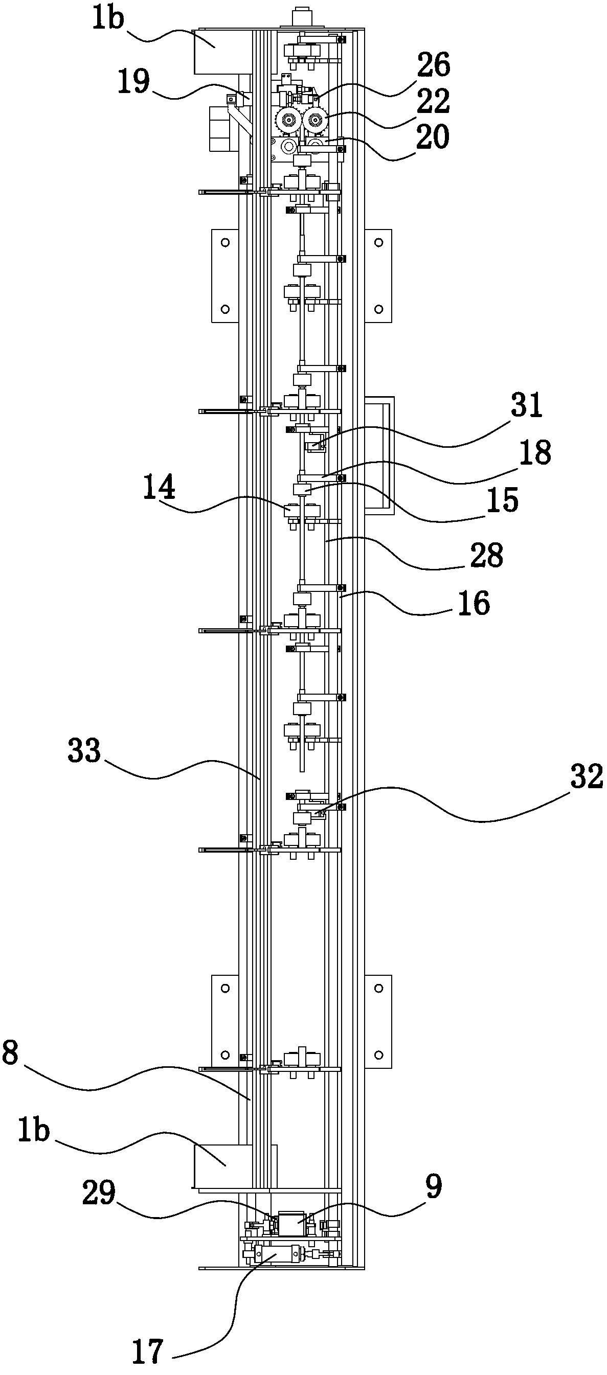
[0026] Such as figure 1 and 2 As shown, the feeding machine includes a frame 1 with a discharge hole 1a, a feeding mechanism, a clamping mechanism and a PLC-based control cabinet 2 fixedly installed on the frame 1, and the feeding mechanism is used to feed the long bar material 33 Convey to the clamping mechanism one by one, the clamping mechanism is used for clamping and fixing the long bar material 33, and the feeder also includes a main conveying mechanism and an auxiliary conveying mechanism for feeding the long bar material 33 on the clamping mechanism Mechanism, feeding mechanism, clamping mechanism, main conveying mechanism and auxiliary conveying mechanism are all installed on the frame 1 and are all electrically ...


PUM


Abstract

The invention provides a feeder and belongs to the technical field of numerically-controlled machine tools. The problem that the conventional feeder is low in feeding efficiency and low in stability is solved. The feeder comprises a frame with a discharging hole, a feeding mechanism, a clamping mechanism, a programmable logic controller (PLC)-based control cabinet which is fixedly arranged on the frame, and a primary conveying mechanism and a secondary conveying mechanism which are used for feeding long bars positioned on the clamping mechanism, wherein the feeding mechanism is used for conveying the long bars to the clamping mechanism one by one; the clamping mechanism is used for fixedly clamping the long bars; and the feeding mechanism, the clamping mechanism, the primary conveying mechanism and the secondary conveying mechanism are arranged on the frame and are electrically connected with the control cabinet. The feeder has the advantages of simple structure, high efficiency and high stability.

Description

technical field [0001] The invention belongs to the technical field of numerical control machine tools, and relates to a feeding machine. Background technique [0002] When processing long bars on CNC lathes, the manual feeding method was generally used in the past. There is no suitable auxiliary feeding device. The conveying position and pushing force are uneven, and the processing quality cannot reach a uniform standard. There are security risks. [0003] With the development and progress of science and technology, people began to design a feeder to assist feeding to replace the original manual feeding method. The feeder uses the driving ejector to push the long bar into the lathe processing position. There are some problems: long The bar is at the front, the ejector is at the back of the long bar, the front end of the ejector is against the rear end of the long bar, and the driving mechanism works to drive the ejector forward to push the long bar to the lathe processing ...

Claims


Application Information

Patent Timeline
IPC IPC(8): B23B15/00
Inventor 朱建群杨云林
Owner 宁波宫铁智能科技有限公司
Why Eureka
Try Eureka