

Air cushion structure and air cushion carrier vehicle
A technology for transporting vehicles and air cushions, applied in the directions of air cushions, transportation and packaging, motor vehicles, etc., to achieve the effect of reducing ground requirements, improving economic benefits, and reducing expensive costs
- Summary
- Abstract
- Description
- Claims
- Application Information
AI Technical Summary
Problems solved by technology
Method used
Image

Examples
Embodiment Construction
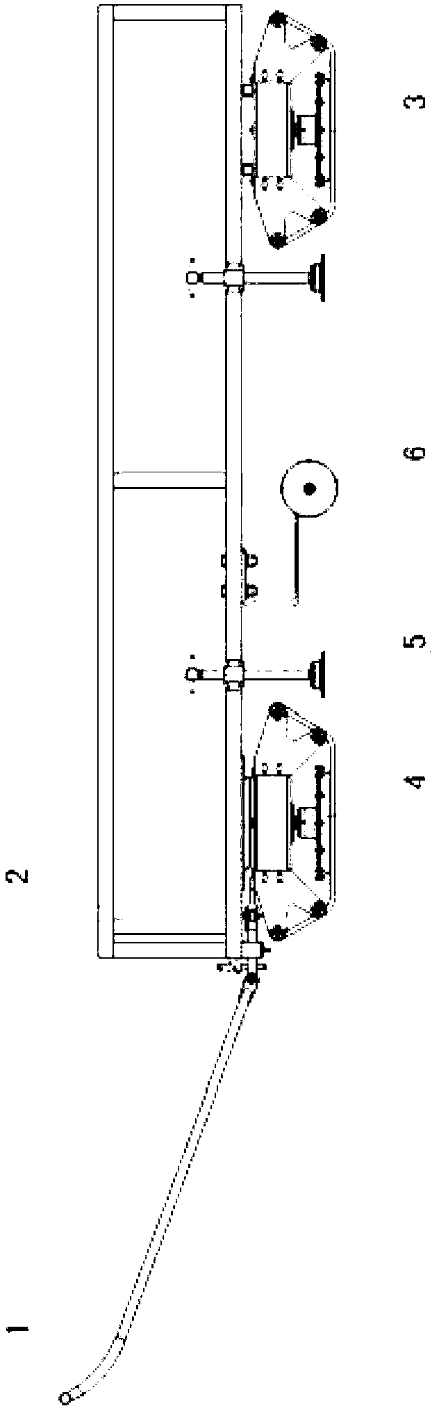
[0019] See attached figure 1 , The air cushion transport vehicle is composed of a drawbar 1, a car body 2, a fixed crawler air cushion 3, a guided crawler air cushion 4, legs 5 and guide wheels 6, etc. The fixed crawler-type air cushion 3 is directly connected with the vehicle body 2, and the guided crawler-type air cushion 4 adds end bearings on the basis of the fixed crawler-type air cushion 3, and then connects with the vehicle body. The air cushion described below uses the fixed crawler belt Formula air cushion 3 is based on launching. The steering control fork is arranged on the crawler-type air cushion 4 of guiding, is connected with drawbar 1 by connecting rod. Guide wheel 6 is installed on a cantilever beam under the car body, is pressed on the ground by certain elastic force, prevents the transport vehicle from laterally slipping in moving.
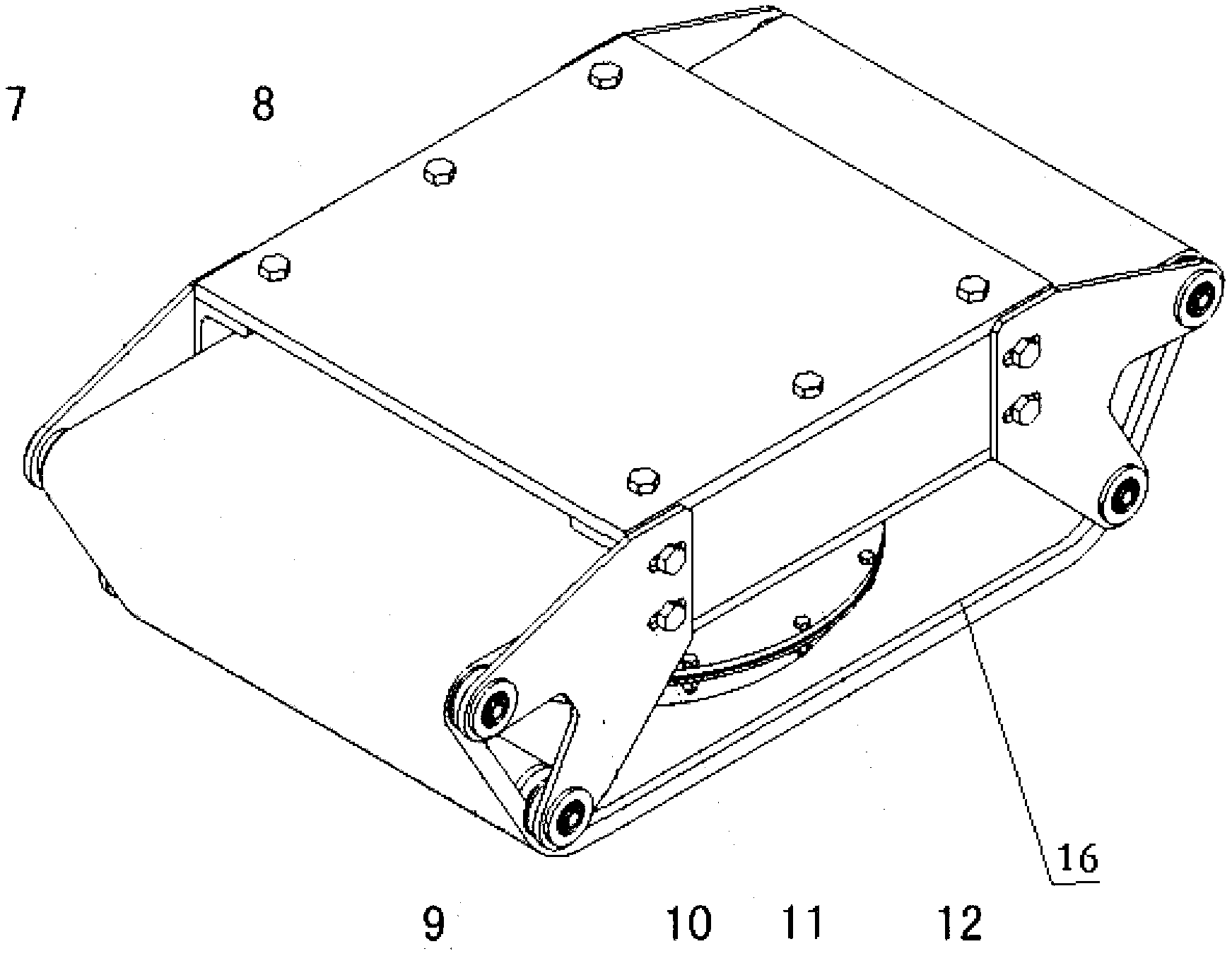
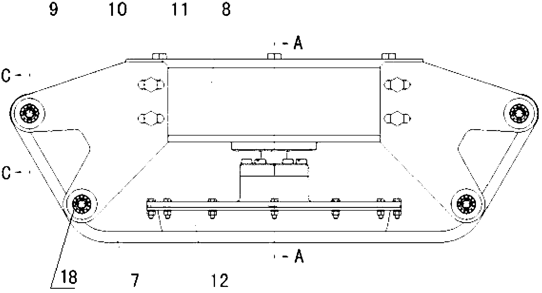
[0020] See attached Figure 2-Figure 5 , The novel crawler-type air cushion of the present application is the design after c...
PUM
 Abstract
Description
Claims
Application Information